User manual
Swipp Flow
About this online version
The English user manual is the official version. Versions in other languages are translations and may differ. If in doubt, the English PDF applies. The manual may be updated, and the version available on swipp.no at any time is the applicable one.
About this manual
This manual defines the agreement between MCrown Auto, and the user regarding the quality assurance responsibility of the product and the rights and obligations regarding after-sales service, and helps you understand how to properly use and maintain the vehicle. It is the basis for you to enjoy the quality assurance service. Please be sure to read this manual carefully before using our products.
Thank you for choosing the car carefully manufactured for you by MCrown Auto.
Warranty
SPECIFIC PARTS RANGE AND QUALITY ASSURANCE PERIOD
| TYPE | PARTS | QUALITY ASSURANCE PERIOD (Time and mileage are determined by whichever comes first) | |
| WARRANTY PERIOD | |||
| Consumable parts | Brake pads, light bulbs, remote control batteries, air conditioners; Filter elements, fuses and common relays (without integrated control unit) | 6 months or 10,000 kilometers | |
| 12V battery | 12 months or 20,000 km | ||
| Wear parts | Tires, wiper blades, oils and fluids | Not covered by the warranty. Replaced as part of normal maintenance at the user’s expense. | |
| Core components | Power battery assembly, motor controller, drive Motor | 5 years or 100,000 km | |
| Other | The vehicle does not include any parts (excluding charging equipment and gifts, please refer to the instructions for specific warranty) | 3 years or 60,000 kilometers | |
| ASSEMBLY | MAIN PARTS | OUR COMPANY EXPLAINS |
| Electric drive system | Power batteries | Power batteries |
| Power battery box | Power battery box | |
| Vehicle Controller | Vehicle Controller | |
| Battery Management System | Battery Management System | |
| Power cables | Power cables | |
| drive motor | drive motor | |
| Motor controller | Motor controller | |
| High-voltage system | High-voltage busbar | High-voltage wiring harness |
| Charging and distribution system assembly | Charging and distribution system assembly | |
| Charging port | AC charging socket | |
| Charging gun | AC charging gun | |
| Steering system | Steering gear assembly | Mechanical, hydraulic and electric steering gears |
| steering column | steering column | |
| Steering joint | Steering intermediate shaft assembly, steering drive shaft | |
| Steering rod (without ball head) | Steering gear inner and outer tie rods | |
| steering knuckle | steering knuckle | |
| Braking system | brake master cylinder | Brake pump assembly, brake master cylinder assembly |
| wheel cylinder | Rear wheel cylinder, brake wheel cylinder, front brake caliper, rear brake caliper | |
| Booster | Vacuum booster assembly, brake master cylinder booster | |
| Brake pedal and bracket | Brake pedal, pedal bracket |
| ASSEMBLY | MAIN PARTS | OUR COMPANY EXPLAINS |
| Drivetrain | Final reducer, differential | reducer |
| Axle | drive shaft | |
| Suspension system | spring | Various springs, front stabilizer bars and stabilizer bar connections |
| control arm | Front lower rocker arm, swing arm and ball pin assembly, control arm, front lower longitudinal member, Tie rod assembly | |
| link | Rear axle assembly, torsion beam assembly | |
| Body | body frame | Body-in-white assembly |
| Subframe | Subframe assembly | |
| longitudinal beam | Front / rear longitudinal beams, side beams, floor longitudinal beams, door sill inner panels | |
| beam | Front / rear cross members, floor cross members | |
| Front and rear door bodies | Front and rear door bodies, including tailgate |
Introduction
This vehicle integrates advanced technology, safety, environmental protection and economy.
This manual provides you with all the necessary information to operate your vehicle safely and efficiently.
Drivers should always be aware that improper vehicle operation may result in accidents and injuries. You must also always comply with the specific laws and regulations of your country. If these requirements differ from those in this manual, the laws and regulations shall prevail.
All staff at MCrown Auto Automobile Co., Ltd.’s authorized repair service center have received excellent professional training and can provide you with comprehensive and satisfactory service. When maintenance and repairs are required, please contact the nearest service center. For contact information of the service center, please refer to the “Maintenance Regulations” section, the section “How to query the maintenance service center address book”.
Directional data, such as front, back, left, and right, are based on the direction of travel as the front.
Some of the functional configurations described in this manual are not equipped on all models. This manual may introduce some equipment and functions that are not installed on your vehicle.
Our company is responsible for the revision and explanation of this manual. Revisions to safety-related content will be notified in accordance with regulatory requirements. Some images in this manual are schematic and for reference only. If the images differ from the actual product, the actual product shall prevail.
Using this manual
The table of contents at the beginning of this manual and at the beginning of each chapter provide information for you to find. This manual may be updated. The version available at any time on swipp.no is the applicable version.
Prompt information
Overview
- This vehicle is a pure electric vehicle. Some of its operations and characteristics differ from those of traditional fuel vehicles. Therefore, please read this manual carefully before using the vehicle.
- The vehicle is powered by electricity. There are two batteries on the vehicle. One is the power battery, which is located under the chassis of the vehicle and provides driving power for the vehicle. other is a common 12V car battery, located in the front cabin, which provides power for instruments, lights and corresponding control modules.
- The power battery uses AC power (i.e., standard household power) as the charging power source. When charging with household AC power, ensure that all wires, sockets, and plugs in the charging circuit are capable of the load. Always have a professional electrician install the charging circuit. The charging circuit must be properly grounded and equipped with a main switch and leakage protection device.
High-voltage safety
- The orange cables on the vehicle are high-voltage cables. Please do not touch them. Warning signs are affixed to the housings of high-voltage components. Please pay special attention.
- The vehicle is used before entering the high pressure state Therefore, do not use lights, audio, air conditioning, etc. for a long time at this time, so as to avoid the 12V battery being exhausted and causing the vehicle to be unable to start. The amount is insufficient and the 12V battery must be charged first.
- After the vehicle enters the high-voltage state, it is mainly powered by the power battery, and the lights, air conditioning, etc. can be used for a long time. The power battery begins to charge the 12V battery.
- In winter, the discharge performance of a vehicle’s power battery decreases as the temperature drops. This performance change is reversible as the temperature rises. It is recommended that you avoid sudden acceleration and prolonged high-speed driving in low-temperature conditions. Plan your trip carefully and charge your vehicle promptly.
- The backend server terminal device will read GB/T Vehicle data specified in 32960.3-2016, drive motor data, extreme value data, vehicle location data, alarm data, rechargeable energy storage device voltage data, rechargeable energy storage device temperature data, and user-defined data. If the backend server terminal device detects an anomaly in your vehicle’s operating data, our service personnel may contact you. In this case, your support and cooperation are needed to promptly resolve any potential risks.
Safety in case of accident
- When a vehicle accident occurs: If time permits, turn off the vehicle’s power, apply the parking brake, turn on the hazard warning lights and put up the warning triangle, exit the vehicle and contact a service center immediately. If time does not permit, such as if there is a fire or a strong burning odor, immediately turn off the vehicle’s power, apply the parking brake, and escape.
- If the fire is large or growing rapidly, immediately move away from the vehicle and call the fire department (110). If the fire is small, use a water-based fire extinguisher to extinguish the fire and keep a safe distance from the fire source.
- If you need to replace the power battery, please be sure to return the old battery to a designated MCrown Auto recycling service outlet for recycling. Careless disposal of power batteries can pollute the environment and even cause personal injury. Relevant laws and regulations also require that such waste be recycled.
- When the power bar on the instrument cluster displays red, it indicates the battery is low. It is recommended that you charge the battery as soon as possible. Do not allow the battery to run out before charging, as this will shorten the battery’s service life. During vehicle use, it is recommended that you fully charge the battery at least once every two weeks for maintenance.
Keys, doors and windows
Key
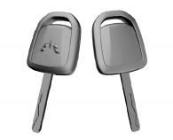
STRAIGHT KEY TYPE I *
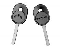
STRAIGHT KEY TYPE II *
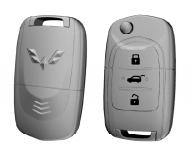
FOLDING REMOTE CONTROL KEY *
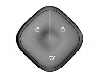
SMART KEY *
Each new car is equipped with a remote control key and a candy bar key. Please keep the candy bar key as a spare. use. Depending on the configuration, some models are equipped with a touchless key entry function. Please do not leave the key in the car for a long time. To avoid excessive power consumption. For safety reasons, please keep the key number plate in a safe place to prevent others from illegally making keys. The keys equipped for different models may be different, please refer to the actual vehicle.
Folding remote control key *
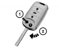
PRESS RELEASE BUTTON ①
As shown in the figure, press the release button ①, The mechanical key will pop out automatically. After use, fold the mechanical key back in.
Keyless entry *
The smart key is equipped with a contactless entry function, which automatically unlocks or locks the vehicle as you approach or move away from it. With this function enabled, the vehicle automatically unlocks when you bring the smart key within 1.5 meters of the vehicle; it automatically powers down and locks when you move the smart key more than 3.5 meters away from the vehicle.
1. Open or close with no-touch key
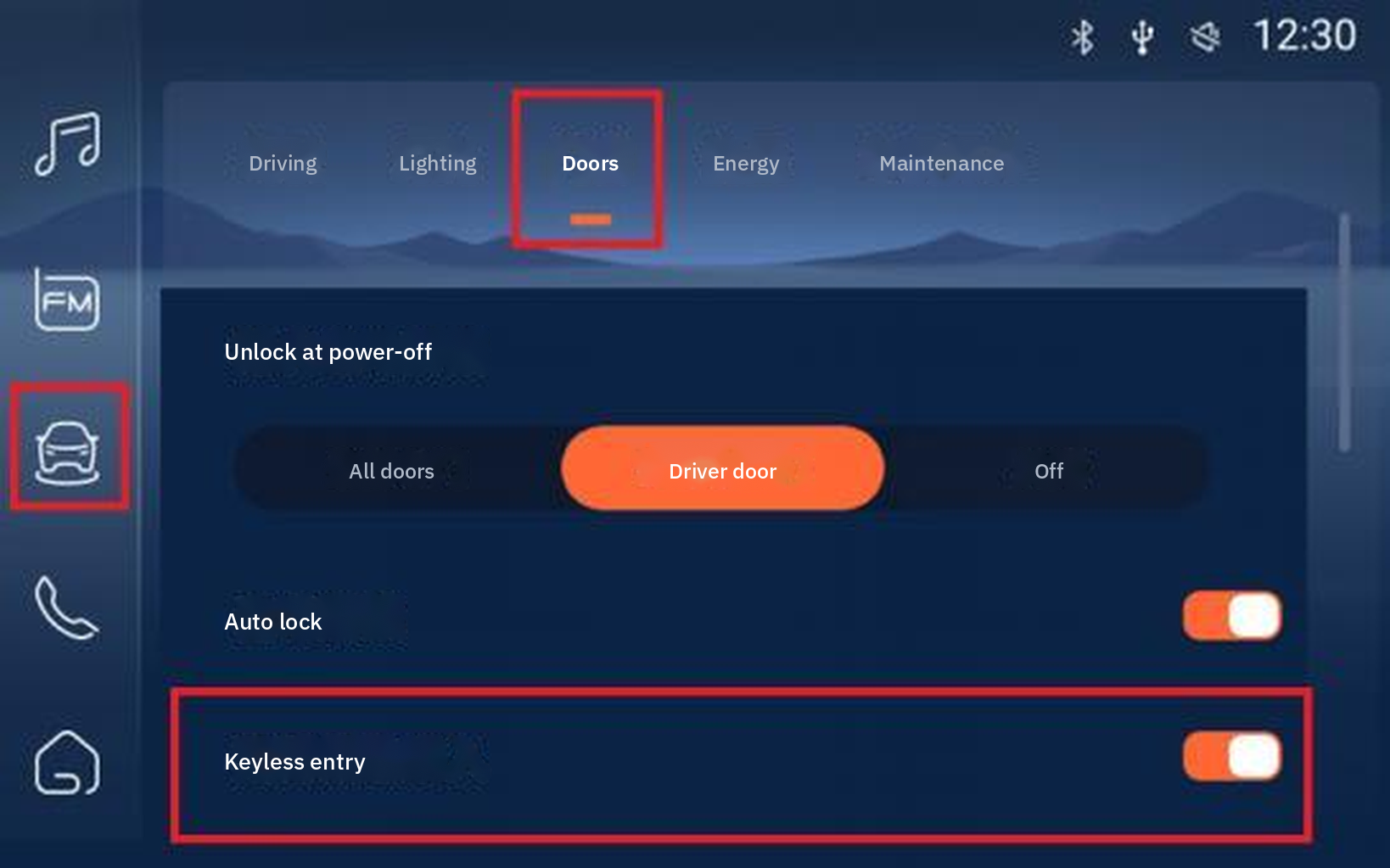
KEYLESS ENTRY SETTING SCREEN
The [Keyless Entry] function can be set in the vehicle’s central control screen [Vehicle Control - Doors and Windows].
- Unlocking with keyless key Unlock triggering conditions (all of the following conditions must be met):
(1) The driver’s door is locked. (2) The touchless key function has been enabled through the vehicle settings. (3) The key is not disabled. (4) There is a smart key in the effective area outside the vehicle.
Lock:
(1) All doors (including the tailgate) are closed. (2) The driver’s door is unlocked. (3) There is no collision or the collision shield lock function has been released. (4) The touchless key function has been enabled through the vehicle settings. (5) The key is not disabled. (6) The smart key is not in the vehicle and has left the valid area outside the vehicle.
Remote door locking system
In the absence of obstructions, the effective distance of the remote control is about 15 meters.
Q: Remote lock button. After all doors are closed, press it once to lock all doors and the hazard warning lights will flash twice, entering anti-theft mode. a: Remote unlock button. Press once to unlock all doors, flash the hazard warning lights once, and release the anti-theft status. Y: Tailgate unlock button. Press and hold for about 3 seconds to unlock the tailgate.
Car search function *
Quickly press the remote lock button twice to trigger the vehicle search function, the horn sounds three times, and the hazard warning lights flash 20 times.
Door lock and anti-theft mode activation
- Close all car windows.
- All passengers leave the car.
- Close all doors, the hood and the tailgate.
- Press and release the remote lock button. All doors lock. The hazard warning lights flash twice, and the anti-theft system is activated.
Unlocking the doors and disabling anti-theft mode
Press the door unlock button on the remote control once.
Lock function alarm
If the door lock conditions are not met, if you press the remote lock button, the horn will beep 3 times and the hazard warning lights will flash 3 times, indicating that the door has not been locked successfully. These situations include:
- A door is not closed properly (including the tailgate);
- The door lock is in thermal protection state.
Automatic door locking *
When all doors are closed and the vehicle speed exceeds 10 km/h, all doors will be automatically locked.
Automatic relock *
The key is not within the unlocking range. After the car is successfully armed, if the arming is lifted but no side door is opened within 30 seconds, the car will be locked again.
Automatic unlock *
The door lock state is locked. According to the vehicle configuration, when the power switch (if equipped) is turned from ON position switching to ACC gear, or the gear is changed from D gear, When the R gear is switched to the P gear, the door will be unlocked automatically.
Transmitter
Each transmitter is electronically coded to prevent other transmitters from being able to open your doors. If your transmitter is lost or stolen, it’s recommended to visit a dealership as soon as possible to replace it. If you need to replace one or more transmitters, bring your existing transmitter with you to the dealership. When the dealership fits the replacement transmitter to your vehicle, the existing transmitter must also be matched to the new encoding. Once the new transmitter is electronically encoded, the lost transmitter will no longer be able to unlock your vehicle.
Transmitter automatically stops transmitting signals *
The transmitter has an automatic stop signal transmission function to prevent unnecessary battery loss due to misoperation. Press and hold any button on the remote control for a certain period of time (about 10 seconds). The transmitter will automatically stop transmitting signals. Releasing the button will cancel the automatic stop function.
Fault
If the remote control does not work properly, it may be due to the following reasons:
- The signal is out of range;
- the remote control battery is too low;
- the signal is interfered with by external environmental factors and other high-power radio signals (such as base stations, transmission towers, etc.);
- or there are other obstacles blocking the signal.
Replacement battery
The remote control on the key has a lithium battery, which can be used for 2 years. If the key is powered on, it indicates that the battery is low. Please replace the battery in time. The battery in the key cannot be charged.
Door locks
Open the car door
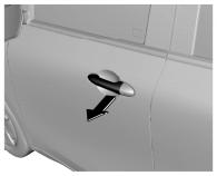
DOOR HANDLE
Open car door from the outside or inside, unlock the vehicle, then pull the exterior or interior door handle.
Mechanical lock
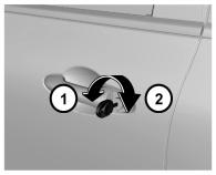
① UNLOCK ② LOCK
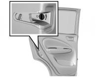
MANUAL REAR-DOOR LOCK KNOB
To lock the door with the key from outside the vehicle, insert the key and turn it clockwise. To unlock, turn the key counterclockwise.
How to lock the doors when the vehicle is powered off
If the vehicle loses power, such as the battery is dead or the positive and negative poles are disconnected, the central door locking system will not work. If you do not want to lock the car door manually, you need to lock the car door manually.
Open the right front door and both rear doors (if equipped), Locate the knob on the inside of the door lock (as shown in the picture above). Note that this is not the knob for the child safety door lock. Use the key to turn the knob in the direction of the arrow to lock the door, and then try to pull the outside handle to confirm that the door is locked. If you need to open the door at this time, please pull the inside handle first. For the left front door, insert the key into the keyhole on the outside door handle and turn it clockwise to lock the door. Please refer to the previous section [Mechanical Lock] for details.
Locking and unlocking doors from inside the vehicle
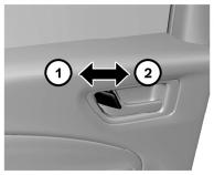
① UNLOCK ② LOCK
To lock the doors from the inside, close the door and then press the door lock button forward. To unlock, pull the door lock button backward.
Child safety door locks *
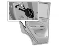
CHILD SAFETY DOOR LOCK
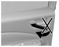
OPEN FROM OUTSIDE WHEN LOCKED
The rear doors of this vehicle (if equipped) are equipped with child safety door locks. The purpose of the child safety door locks is to prevent passengers (especially children) from pulling the door handle and accidentally opening the rear doors.
To activate the child safety door locks:
- Open the rear door you want to lock.
- Locate the grooved knob for the child safety gate near the center of the door edge.
- Insert the key into the slot and turn it in the direction indicated by the arrow.
When the child safety door lock is activated, the door cannot be opened from inside the car. You need to pull the door handle from outside the car to open the door. To lock, insert the key into the slot and turn it in the opposite direction.
Central door locking system
With the central locking system, you can not only lock and unlock the doors with the remote control, but you can also unlock and lock the doors (including the tailgate) using the door lock toggle button on the driver’s door.
Car door
Open the tailgate
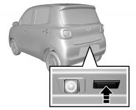
OPEN THE TAILGATE
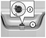
TAILGATE LOCK MAINTENANCE HOLE
Unlock the vehicle first, then press the tailgate switch to open the tailgate. When opening the tailgate, ensure that you and others keep your body away from the tailgate to avoid personal injury caused by the tailgate popping up. When closing the tailgate, make sure that your hands and other parts of your body are completely out of the tailgate closing area.
Tailgate lock maintenance hole
If all other tailgate opening methods fail, you can temporarily open the tailgate by following the steps below:
- Adjust the seat and enter the luggage compartment.
- Open the decorative cover outside the tailgate lock, as shown in the figure ①.
- Use a suitable tool, such as a flathead screwdriver, to insert it into the groove (see ② in the figure). Turn clockwise to unlock the tailgate.
Keyless door locking system (PEPS) *
Some models are equipped with a keyless door lock system. You only need to bring the remote control key close to the door within a certain range. You can lock or unlock the car door conveniently from the door. You don’t need to take the key out of your pocket to lock or unlock it remotely.
Keyless entry *
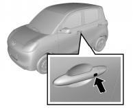
KEYLESS UNLOCK / LOCK BUTTON
With the doors locked and the vehicle powered off, bring the valid key within a certain distance (approximately 1.2 meters) of the front door handle. The system successfully authenticates the key. Press the button to unlock all doors (excluding the tailgate) and the hazard warning lights flash once.
Keyless Leave *
With all doors closed and the vehicle powered off, hold the valid key within a certain distance (approximately 1.2 meters) of the front door handle and press the button on the door handle. The system will authenticate the key and, upon successful authentication, all doors will lock. The hazard lights will flash twice.
If the following situations occur, after pressing the button on the door handle, the system will issue an alarm and the horn will beep 3 times, the hazard warning lights flash 3 times, indicating that the doors are not locked. The possible situations are as follows:
- One of the car doors was not closed properly.
- There are keys (not straight keys) in the vehicle. Please check each one and lock it again.
Front hatch
Open the front hood
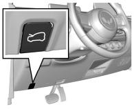
HOOD RELEASE HANDLE
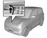
OPEN THE HOOD
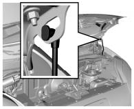
HOOD SUPPORT BAR
- Pull the hood release handle on the lower left side of the instrument panel.
- After the hood is slightly open, reach under the front edge of the hood, pull up the hood release handle as shown in the figure above, and fully open the hood.
- Disengage the hood support bar from the securing clips. Insert the free end of the support rod into the slot.
Close the front hatch
- While holding the front hatch to prevent it from falling, remove the support bar from the slot, and then snap it securely into the securing clip.
- Keep your hands and other body parts completely away from the front compartment and the front hood to the edge of the vehicle body.
- Slowly lower the front hatch cover and let it fall freely when the front edge of the front hatch cover is about 30 cm above the beam.
- Be sure to check that the front hatch is locked in place.
Exterior rearview mirror
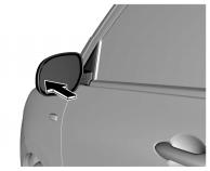
EXTERIOR REARVIEW MIRROR
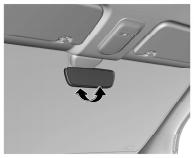
INTERIOR REARVIEW MIRROR
Before driving, check the visibility in all mirrors.
Adjusting the exterior mirrors
Press the edge of the lens with your hand to adjust it to a suitable viewing angle.
Folding exterior mirrors
To ensure pedestrian safety, the exterior mirrors can be folded from their normal mounting positions to the front and rear in the event of a collision with sufficient force. They can be reset by hand.
Interior rearview mirror
The interior rearview mirror can be adjusted to a suitable viewing angle by flipping the mirror frame. Depending on the vehicle configuration, some models have a USB port for driving recorders on the back of the rearview mirror *. [Instruments and Controls - Controls - Dash Cam USB Port *] Contents.
Car windows
Power windows
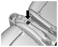
TYPE I : SWITCH BETWEEN FRONT SEATS
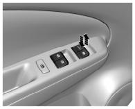
TYPE II : DOOR ARMREST PANEL
Type I: The window lift switch is located between the front seats. After the vehicle is powered on, the left and right windows can be controlled by the left and right switches respectively.
Type II: The window lift switches are located on the door armrest panel. After the vehicle is powered on, the power windows can be controlled using the switches on each door armrest panel. All power windows can also be controlled using the combination switch on the driver’s side. Press the front of the switch to lower the glass, and lift the front of the switch to raise the glass. When the window reaches the desired position, release the switch.
Driver’s side window one-touch down *
The driver’s side window on some models has a one-touch down feature. Press the switch all the way down (2nd position) and release it. The window will automatically lower until it fully opens. To stop the window from lowering, pull the switch up and release it (a single touch).
Power window locking button *
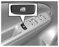
POWER WINDOW LOCKING BUTTON
The power window lock button locks the power window switches on the front passenger side and rear doors. Press the button and the other power window switches are locked and can only be operated through the driver’s window control panel. Press the button again to unlock.
Sun visor
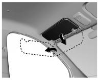
SUN VISOR
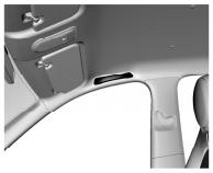
ASSISTIVE HANDRAILS
Your vehicle is equipped with sun visors on the front seats to reduce glare for passengers in the front seats. The sun visor can be swung up and down as well as sideways. The driver’s sun visor is available in some models with a vanity mirror *.
Assistive handrails
The assistive armrest makes it easier for you and your passengers to get in and out of the vehicle. At high speeds, holding onto the armrest helps you stay seated.
Seats, protective devices
Front seats
Seat position and backrest normal condition
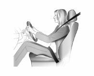
NORMAL SEATING POSITION
- When seated, back up as far as possible to the backrest. Adjust the distance between the seat and pedals so that your legs are slightly bent when you press the pedals. The passenger seat should slide back as far as possible.
- When seated, lean your shoulders back against the backrest as far as possible. Adjust the backrest tilt so that your arms can easily reach the steering wheel with a slight bend. Keep your shoulders against the backrest when turning the steering wheel. Do not recline the backrest excessively. We recommend that all backrest tilt angles not exceed 25 degrees.
- The seat height should be set so that you can clearly see all directions and all instrument displays. There must be at least a hand’s distance between your head and the headrest. Your thighs should rest comfortably on the seat without feeling constricted.
- When measuring seat depth, the seat’s fore-aft position can be arbitrary. There must be at least a hand’s length from the headlining. Your thighs should rest comfortably on the seat without any pressure.
Seat position adjustment
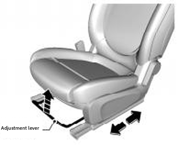
SEAT POSITION ADJUSTMENT LEVER
Pull up the adjustment lever at the front of the seat cushion, adjust the seat forward and backward to the appropriate position, and then release the adjustment lever. Try sliding the seat forward and backward to make sure it is locked in place.
Seat backrest adjustment *
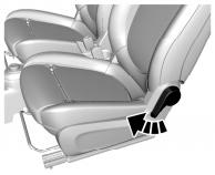
SEAT BACKREST ADJUSTMENT LEVER
Pull up the lever on the outside of the seat cushion, adjust the backrest to the desired angle, and then release the lever. Do not lean on the seatback while adjusting. After adjusting the seatback, try to rock the seatback to make sure it is locked.
One-touch entry and exit for the passenger seat *
The passenger seat has a one-touch slide function. Adjust the passenger seat backrest to the forward position; the seat rails are unlocked and the seat can be moved directly forward or backward to the desired position without unlocking the rails separately. Adjust the backrest backward to the appropriate position and return the seat slide to the locked state.
Seat layout diagram
Swipp Flow has two seats: the driver’s seat and the front passenger seat.
Seat belt
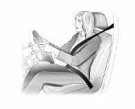
SEAT BELT
Seat belts provide excellent protection in the event of an accident and are required by law. Seat belts are designed primarily for adults and are suitable for passengers taller than 150 cm and weighing more than 36 kg. Children under 12 should use an appropriate child restraint system based on their size. Regularly inspect all seat belt system parts for wear, damage, and proper function. Replace any damaged parts. After an accident, we strongly recommend that you contact an authorized service center to replace the seat belts and any activated seat belt tensioners.
Seat belt force limiters *
Assembled on the driver’s seat belt, it can reduce the stress applied to the body by damping the seat belt in the event of a collision. A seat belt pretensioner that has been activated must be replaced by an authorized service center. A seat belt pretensioner can only be activated once.
Wear
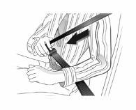
ROUTE THE BELT WITHOUT TWISTING
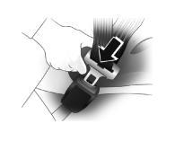
INSERT TONGUE UNTIL IT CLICKS
Pull the seat belt from the retractor and guide it around the body without twisting it. The shoulder belt should be diagonally across the shoulders, but not touching the neck or sliding off the shoulders. The lap belt should be as low as possible across the hips.
Insert the lock tongue forward (inserting the lock tongue in reverse will cause the seat belt to twist, resulting in cuts or even life-threatening injuries during a collision!) into the buckle that matches this seat, until you hear a “click” locking sound. the lock is secure by pulling it. You can adjust the tightness of the crotch belt by pulling the shoulder belt firmly. When the vehicle is moving steadily, the passenger can move slightly, and the seat belt can be pulled out or retracted as the passenger moves slowly.
Unfasten
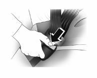
PRESS THE RED BUTTON TO RELEASE
To release the seat belt, press the red button on the buckle. The tongue will automatically pop out and the belt will rewind. Rewinding or pulling out the belt too quickly can cause the belt to become locked. Allow the webbing to slacken before you can pull it out smoothly.
Seat belt use during pregnancy
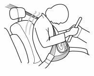
LAP BELT LOW ACROSS THE HIPS
Seat belts provide protection for everyone, including pregnant women. Like all passengers, they are more likely to suffer serious injury if they do not wear a seat belt. Pregnant women should wear a lap / shoulder belt, and the lap belt should be worn as low as possible throughout pregnancy. The best way to protect the fetus is to protect the mother. When a seat belt is worn correctly, the fetus is less vulnerable to injury in a crash.
Child seats
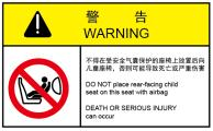
REAR-FACING RESTRAINT WARNING LABEL
Information on the suitability of child restraint systems for different seating positions
| QUALITY GROUP | FRONT PASSENGER |
| Group 0 : <10 kg | X |
| Group 0+ : <13 kg | X |
| Group I : 9 kg~18 kg | X |
| Group II : 15 kg~25 kg | X |
| Group III : 22 kg~36 kg | X |
Information on the suitability of child restraint systems for different seating positions (ISOFIX)
| QUALITY GROUP | SIZE CATEGORY | FIXED MODULE | FRONT PASSENGER | OTHER LOCATIONS |
| Portable bed | F | ISO/L1 | X | X |
| G | ISO/L2 | X | X | |
| (1) | ||||
| Group 0 : < 10 kg | E | ISO/R1 | X | X |
| (1) | ||||
| Group 0+ : < 13 kg | E | ISO/R1 | X | X |
| D | ISO/R2 | X | X | |
| C | ISO/R3 | X | X | |
| (1) | ||||
| Group I : 9 kg~18 kg | D | ISO/R2 | X | X |
| C | ISO/R3 | X | X | |
| B | ISO/F2 | X | X | |
| B1 | ISO/F2X | X | X | |
| A | ISO/F3 | X | X | |
| (1) | ||||
| Group II : 15 kg~25 kg | (1) | |||
| Group III : 22 kg~36 kg | (1) | |||
Airbag system

AIRBAG SYSTEM
The car may have the following airbags:
- Driver front airbag.
- Passenger front airbag (if equipped).
All vehicle air bags are marked on a trim panel or label near the opening where they deploy. “AIRBAG” is located in the center of the steering wheel for the driver’s airbag. Airbags provide additional protection when seat belts are worn correctly.
Airbag indicator light
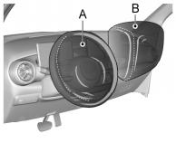
AIRBAG LOCATIONS: A DRIVER, B PASSENGER
There is an airbag status indicator on the instrument panel light, which displays an airbag-shaped symbol. The system checks the airbag circuit system for any faults and displays the corresponding indicator light. For more information, see the “Instruments and Controls” section.
Airbag location
As shown in Figure A above, the driver’s front airbag is located in the center of the steering wheel. As shown in Figure B above, the passenger front airbag (if equipped) is located on the passenger side instrument panel.
When should airbags inflate?
Frontal airbags are designed to inflate in moderate to severe frontal collisions or near frontal collisions to help reduce the risk of serious driver head and chest injuries. Whether the front airbag inflates does not depend primarily on the vehicle’s speed, but rather on the object being hit, the direction of the impact, and the vehicle’s deceleration per unit time during the collision.
Frontal airbags may inflate at different collision speeds. It depends on whether the vehicle hits the object straight or at an angle at the moment of collision, and whether the object is stationary or moving. The front airbags are designed differently for each car, so the inflating collision conditions will be different.
Frontal airbags will not inflate in a vehicle rollover, rear impact, or many side collisions. Frontal airbags will inflate in mild frontal or near-frontal collisions, side front or diagonal collisions, and collisions with cylindrical objects (such as utility poles, tree trunks, etc.). The airbag may not inflate if the vehicle is rear-ended and hit under the sidewall of a large vehicle (truck, etc.), or if the vehicle is hit from the side.
How do airbags inflate?
During the inflation process, the sensing system sends an electronic signal that triggers the inflator to release gas into the airbag, causing the airbag to inflate and pop out from the cover. The inflator, airbag, and related components are all part of the airbag module.
How do airbags provide protection?
Airbags supplement the protection provided by seatbelts by distributing the impact force more evenly across the driver’s body. However, in some collisions where the driver’s body is not moving toward the airbag, or in collisions where an object intrudes into the vehicle, airbags may not provide adequate protection. Airbags should be considered solely as a supplement to seatbelts.
What will I see when the airbag inflates?
After airbags inflate, they deflate quickly. Some people may not even notice the airbag has inflated because it deflates so quickly. Some smoke and dust may also escape from the airbag vents after a deflation.
If the vehicle’s electrical system remains functional after a collision, the vehicle is equipped with a function that automatically unlocks the doors, activates the hazard warning lights, and shuts off the high-voltage system after the airbags inflate. The driver can use the corresponding function switches to lock the doors, turn off the interior lights, and deactivate the hazard warning lights. Airbag deployment may also cause windshield breakage.
- Airbags are designed to inflate only once. After airbag inflation, some parts of the airbag system need to be replaced. If these parts are not replaced, the airbag system will not provide protection in the next collision. Replaceable airbag system parts include the airbag module, airbag control module, seatbelt pretensioners, and other components.
- Work related to the airbag system should only be performed by qualified technicians. Improper maintenance may cause the airbag system to malfunction. Please have your vehicle serviced at an authorized service center for repair and maintenance.
Other situations in which airbags may inflate (deploy)
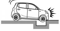
HITTING A CURB, SIDEWALK EDGE, OR HARD SURFACE
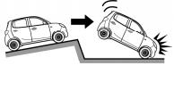
FALL INTO OR JUMP OVER A DEEP PIT
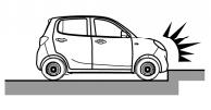
SEVERE IMPACT TO THE UNDERSIDE
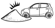
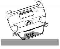
ROLLOVER, FALL FROM HEIGHT, TUMBLE
In addition to collisions, airbags may also inflate if the vehicle sustains a severe impact to the underside, if the wheels hit the ground hard, or if the vehicle falls.
Collisions in which the front airbag may NOT inflate
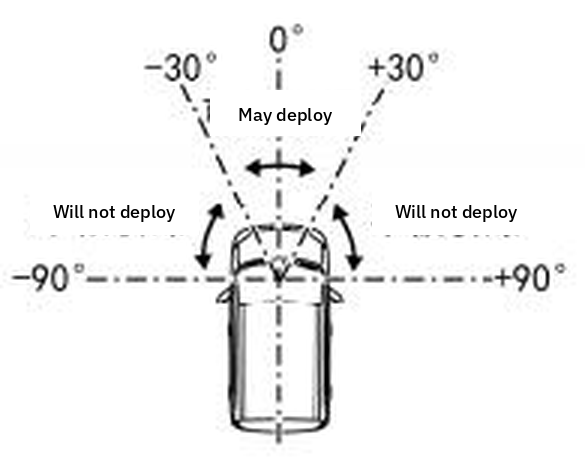
INFLATION ANGLE RANGE DIAGRAM
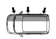
30° TO THE LONGITUDINAL DIRECTION
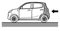
REAR-ENDED
HITTING DEFORMABLE OBJECTS SUCH AS SAND PILES,
GUARDRAILS, PILLARS, TREES, ETC.
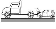
GET UNDER THE VEHICLE IN FRONT, ESPECIALLY THE TRUCK
Frontal airbags generally do not inflate when the vehicle is hit from the side, rear-end, rolls over, or in a low-speed frontal collision. Regardless of the type of collision, frontal airbags will only inflate if the vehicle experiences sufficient forward deceleration.
Important recommendations
Children in the vehicle
Swipp Flow has no second row of seats. According to accident statistics, children aged 12 or under are safest in a rear seat with appropriate protective devices. If the vehicle is equipped with a front passenger airbag, it cannot be deactivated. Never place a rear-facing child restraint system in the front passenger seat if a front passenger airbag is fitted.
Correct sitting method for adults and teenagers
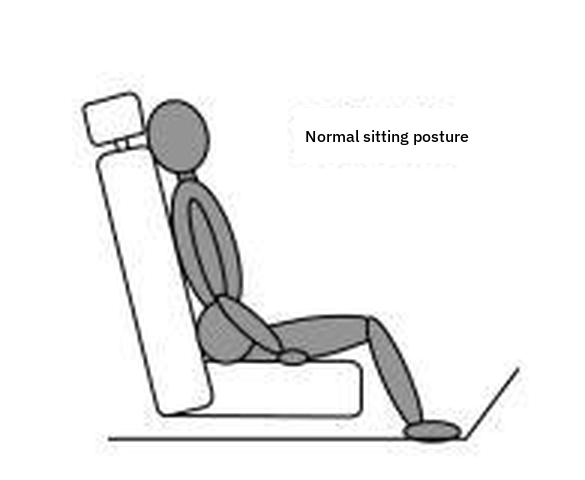
CORRECT SITTING POSTURE
Sit in the driver’s seat in the correct way, can play the role of airbag more safely and effectively. The best riding posture for adults and teenagers should be:
- Move the seat back to a comfortable and safe position
Being further away from the air bag assembly does not diminish the effectiveness of the air bag in protecting you. The farther away from the air bag assembly, the less dangerous it is when the air bag suddenly inflates with great force. But be sure not to move the driver’s seat back too far to prevent the driver from comfortably operating the steering wheel, pedals, and other instrument controls.
- Tilt the chair back slightly forward without leaning forward
Slightly tilt the back of the seat and sit with your back against it. Do not lean your body or otherwise bring your body closer to the airbag assembly, or bring it closer than 15 cm. Do not place any part of your body on the plastic decorative shell of the airbag assembly. On or near the center of the steering wheel. Try to keep your head and body at least 25 to 30 centimeters away from the airbag. The farther away, the safer it is.
- Do not place objects, children, or pets between you and the air bag module
Placing objects on, above, or near the plastic cover that houses the air bag assembly could project the object onto your face and upper body when the air bag inflates. Children and pets should not ride on the laps of other passengers. Do not place objects that could injure someone when the air bag inflates on your lap.
Do not install non-original accessories on the steering wheel and instrument panel, as these accessories may prevent airbag inflation, affect system operation, or strike passengers, causing injury.
If you resell your vehicle to someone else, please explain to the new owner that the vehicle is equipped with an air bag system and recommend that he or she read this manual. Sit as far back as possible while maintaining control of the vehicle. If you sit too close to the airbag, it may inflate and cause serious injury or death. To ensure maximum safety in all types of collisions, all passengers (including the driver) must always wear seat belts to minimize the risk of serious injury or death in the event of a collision. Do not sit or lean too close to the airbag while the vehicle is moving.
Storage
Storage box
Dashboard storage compartment
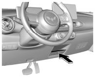
DASHBOARD STORAGE COMPARTMENT
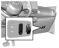
HIDDEN HOOK
As shown in the figure, a storage slot is provided in the lower center portion of the instrument panel.
Sub-dashboard storage box
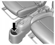
SUB-DASHBOARD STORAGE BOX
As you can see in the picture above, the center console has open storage space between the front seats where you can place your belongings.
Cup holder
Cup holder *
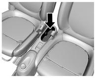
CUP HOLDER *
Cup holders (if equipped) are located on the center console.
Door storage slots and armrests
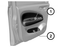
DOOR STORAGE SLOTS AND ARMRESTS
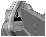
TRUNK STORAGE COMPARTMENT
The doors are equipped with storage slots and armrests.
Trunk storage compartment
The trunk storage slots are located on both sides of the trunk for you to place your items.
Loading information
Notes on loading cargo
1. Precautions for loading cargo
- Heavy objects in the luggage compartment should be against the seatbacks. Make sure the seatbacks are engaged firmly. If you want to stack items in layers, heavy items should be placed at the bottom.
- Loose items in the luggage compartment should be secured to prevent them from sliding. Do not place any unsecured items in the vehicle.
- Do not load items above the top edge of the seatback.
- No objects may be placed on the dashboard, and it is prohibited to cover the sensors and airbag devices on the dashboard.
- The load must not obstruct the operation of the pedals, parking brake and gearshift, nor restrict the driver’s freedom of movement.
- Do not drive with the tailgate open.
Instruments and Controls
Dashboard
Instrument panel type I *
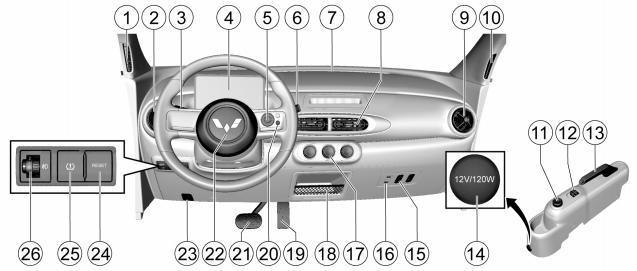
INSTRUMENT PANEL TYPE I *
- Window defrost vent (left)
- Side vents (left)
- Headlight and turn signal switch
- Instrument cluster
- Multi-function steering wheel buttons
- Wiper and washer switch
- Front windshield vents
- Central vents
- Side vents (right)
- Window defrost vent (right)
- Shift knob
- Power window switch (if equipped)
- Parking brake
- 12V power interface
- Hidden hook
- USB interface
- Air conditioning control panel
- Dashboard center storage box
- Accelerator pedal
- Economy / Sports mode switch button
- Brake pedal
- Horn button / airbag
- Front hood release handle
- Combination instrument setting (RESET) button
- Tire pressure reset switch
- Headlamp beam adjustment switch
Instrument panel type II *
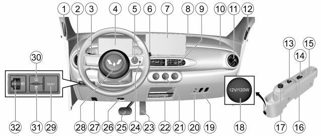
INSTRUMENT PANEL TYPE II *
- Window defrost vent (left)
- Side vents (left)
- Headlight and turn signal switch
- Instrument cluster
- Multi-function steering wheel buttons
- Wiper and washer switch
- Multimedia display screen
- Front windshield vents
- Central vents
- Co-pilot front airbag
- Side vents (right)
- Window defrost vent (right)
- Power window switch (if equipped)
- Automatic parking switch
- Cup holder
- Electronic parking switch
- Shift knob
- 12V power interface
- Hidden hook
- USB interface
- Air conditioning control panel
- Dashboard center storage box
- Accelerator pedal
- Economy / Sports mode switch button
- Brake pedal
- Emergency power off switch
- Front hood release handle
- Horn button / airbag
- Instrument combination setting (RESET) button
- Tire pressure reset switch
- Electronic Stability System Off (ESC OFF) button
- Headlamp beam adjustment switch
Control device
Horn
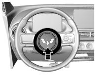
HORN
Press the center of the steering wheel to sound the horn.
Windshield wipers
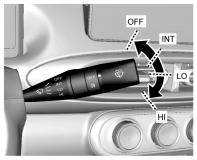
WIPER / WASHER STALK
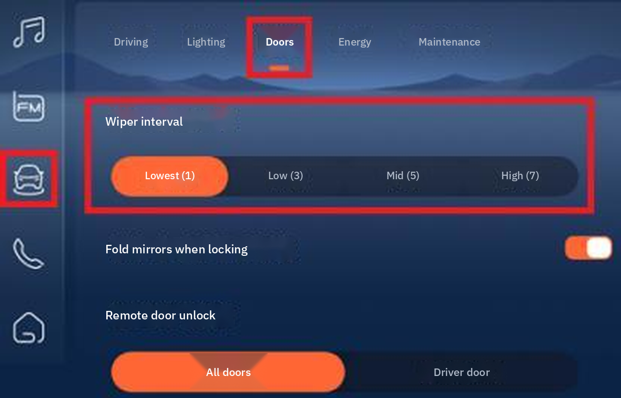
WIPER INTERVAL SETTING ON THE CENTRAL CONTROL
SCREEN
To use the windshield wipers, first turn on the vehicle’s power supply and then move the windshield wiper / washer stalk. The windshield wipers have the following working positions:
OFF: The system is turned off. INT: Intermittent wiper.
LO: Continuous wiping at low speed. HI: Continuous wiping at high speed.
Depending on the configuration, some models can set the wiper interval time on the car’s central control screen. Click the [Vehicle Control] icon in the left navigation bar, drop-down menu, or all applications to enter the [Doors and Windows] settings interface, where you can set the [Wiper Interval].
Front windshield washer
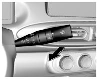
PULL THE LEVER TOWARD THE STEERING WHEEL
To spray washer fluid on the windshield: Connect the vehicle to the power source. Put wiper / washer lever toward the steering wheel, and the water pump will immediately spray water to the front windshield; the water will stop spraying after the front washer switch is released. If you pull the lever for more than 1 second, the wipers will run at low speed for 3 cycles before stopping.
Dashboard USB port *
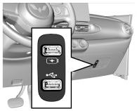
DASHBOARD USB PORT
Depending on the vehicle configuration, the location of the USB port may be different. The USB port is located next to a hidden hook on the passenger side. The USB port can be used to charge mobile phones, etc., and can also be used to connect and play audio. Before use, please connect the vehicle to the power supply. The charging power supply cannot be used when the vehicle is not in the READY state.
12V power supply
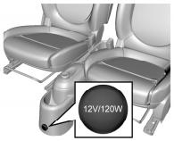
12V POWER SOCKET (12V/120W)
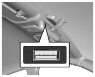
DRIVING RECORDER USB PORT *
As shown in the figure above, the 12V power socket is located below the shift knob. This socket can be used to power 12V electrical appliances with a maximum load current of 10A. The load power is 120W. Before use, turn on the vehicle power. When the vehicle is not in the READY state, the 12V power supply cannot be used.
Driving recorder USB port *
Depending on the vehicle configuration, your vehicle may be equipped with a dashcam USB port located behind the rearview mirror for easy power supply.
E/S button
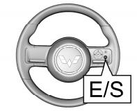
E/S BUTTON ON THE STEERING WHEEL
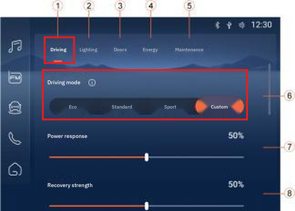
DRIVING MODE ON THE CENTRAL CONTROL SCREEN
Depending on the vehicle configuration, the function of the [E/S button] of different vehicles may be different. Please refer to the actual vehicle for details. Press the [E/S button] on the right side of the steering wheel to switch between three driving modes: economy, sport, and standard.
Some models can also set the driving mode from the car’s central control screen. Click the [Vehicle Control] icon in the left navigation bar, drop-down menu, or all applications on the central control screen to enter the [Driving] settings interface. In [Driving Mode], you can select Economic Mode, Standard Mode, Sport Mode, or Personalized Mode. When Personalized Mode is selected, the “Power Response” and “Recovery Strength” sliders will pop up for setting. In “Personalized Mode” E/S button on the steering wheel is disabled.
RESET (instrument cluster) setting button
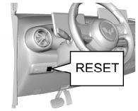
RESET BUTTON ON THE LEFT OF THE INSTRUMENT PANEL
As shown in the figure above, there is a button on the left side of the instrument panel. Short press the button to switch the mileage information (subtotal mileage, total mileage) of the instrument cluster, nearly 50 kilometers of average power consumption, brightness adjustment * Show. When the mileage meter is displayed, long-press the button to reset the mileage meter. When the average power consumption over the past 50 kilometers is displayed, long-press the button to reset the average power consumption. Some models have a brightness adjustment interface. When the brightness adjustment is displayed, long-press the button to adjust the screen brightness.
Warning light gauges and indicators
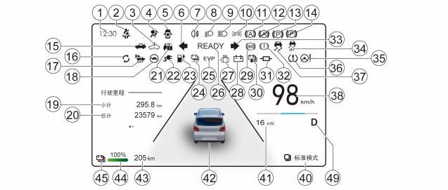
Instrument cluster type I *
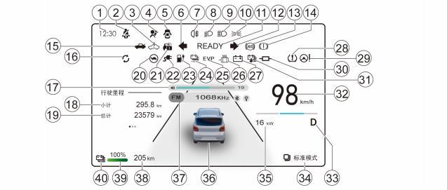
INSTRUMENT CLUSTER TYPE I *
- Time display
- Seat belt not fastened warning light
- System fault warning light
- Airbag malfunction warning light
- Door not closed indicator light
- Left turn indicator / hazard warning flashers
- Rear fog lamp
- Low beam
- High beam
- Position lights
- READY indicator
- Right turn indicator / hazard warning flashers
- Anti-lock braking system (ABS) Malfunction warning light
- Brake system warning light
- Tailgate open indicator light
- Energy recovery indicator light
- Volume display
- Subtotal mileage
- Total mileage
- Drive power limit indicator light
- Anti-theft system indicator light
- Charging cable connection indicator light
- Charging status indicator
- Battery pack heating indicator light
- Vacuum pump fault warning light
- Motor overheat warning light
- Battery fault warning light
- Tire Pressure Monitoring System (TPMS) Malfunction Warning Light
- Electric Power Steering (EPS) Malfunction warning light
- Insulation warning light
- Battery thermal runaway warning light
- Speedometer
- Gear position display
- Driving Mode
- Output power
- Vehicle status display
- Bluetooth host information display
- Cruise range odometer
- Power meter
- Power battery low warning light
Instrument cluster II *
INSTRUMENT CLUSTER II *
- Time display
- Seat belt not fastened warning light
- System fault warning light
- Airbag malfunction warning light
- Door not closed indicator light
- Left turn indicator / hazard warning flashers
- Rear fog lamp
- Low beam
- High beam
- Position lights
- Automatic Handicap Holding (AVH) Working indicator light
- Automatic Handicap Holding (AVH) Malfunction warning light
- Electronic parking brake system (EPB) Working indicator light
- Electronic parking brake system (EPB) Malfunction warning light
- Tailgate open indicator light
- Energy recovery indicator light
- Pedestrian warning sound off indicator light
- Drive power limit indicator light
- Subtotal mileage
- Total mileage
- Anti-theft system indicator light
- Charging cable connection indicator light
- Charging status indicator
- Battery pack heating indicator light
- Vacuum pump fault warning light
- READY indicator
- Motor overheat warning light
- Battery fault warning light
- Anti-lock braking system (ABS) Malfunction warning light
- Battery thermal runaway warning light
- Insulation warning light
- Brake system warning light
- Right turn indicator / hazard warning flashers
- Electronic Stability System Off (ESC OFF) indicator light
- Electronic Power Steering (EPS) Malfunction warning light
- Tire Pressure Monitoring System (TPMS) Malfunction warning light
- Electronic Stability Control (ESC) Status indicator
- Speedometer
- Gear position display
- Driving Mode
- Output power
- Vehicle status display
- Cruise range odometer
- Power meter
- Power battery low warning light
Speedometer
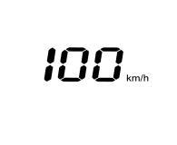
SPEEDOMETER
Displays vehicle speed.
Power meter
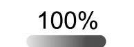
POWER METER
Displays the power level of the drive battery. If the battery power is too low, the low power battery indicator will light up. It is recommended to charge as soon as possible.
Power meter

POWER METER
Displays the power of the battery.
Odometer
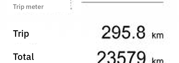
ODOMETER
The subtotal mileage and total mileage are displayed in the same area. Press the RESET key to switch the page. [RESET (instrument cluster) setting button] content.
Range

RANGE
Displays the remaining driving distance.
Gear display
Displays gear status. N: Neutral D: forward gear R: reverse gear P: Park (if equipped)
Driving Mode
Driving Mode (Economy, Standard, Sport) is displayed on the lower right side of the instrument cluster. To switch driving modes, press the E/S button on the right side of the steering wheel or use the central control screen (if equipped). See [Instruments and Controls - Controls - E/S Button].
Control indicator light

READY indicator
READY indicator light comes on to indicate that the vehicle is ready to drive. If the READY light is not on, there will be no response when operating the shift knob (the gear cannot be engaged). Conditions for the READY indicator to light up (must be met simultaneously): vehicle is powered on; There are legal keys in the vehicle; brake pedal is depressed.
Charging status indicator
When the vehicle is connected to the power supply, the indicator light will light up briefly and then go out, indicating that the charger is normal. When the vehicle is charging, the indicator light will light up to indicate that it is in charging state. When charging is complete, the indicator light will go out.
Charging cable connection indicator
When the vehicle is powered on, the indicator light will light up briefly and then go out, indicating that the charging circuit is normal. When charging, this indicator lights up to indicate that the charging cable is connected. If the indicator light does not light up during charging, please check whether the charging cable connectors are securely connected.

Energy recovery indicator light
When the vehicle is plugged in, the indicator light illuminates briefly and then turns off, indicating that the indicator light is normal. When the vehicle is traveling at high speeds and the accelerator pedal is released or the brake pedal is pressed, the system determines that the conditions for energy recovery are met and the vehicle begins to regenerate energy. This converts mechanical energy generated during driving into electrical energy and stores it in the power battery, increasing range. When the energy recovery system is operating, the energy recovery indicator on the instrument cluster illuminates, and the power display becomes negative.
Constraints for energy recovery:
- No energy recovery is performed below 0 °C.
- Energy recovery is not performed when the vehicle speed is less than 8 km/h. In addition to the above, energy recovery may not be performed or the energy recovery power may be low under certain operating conditions.
Depending on the configuration, the energy recovery mode and intensity of some models can be adjusted in the following ways:
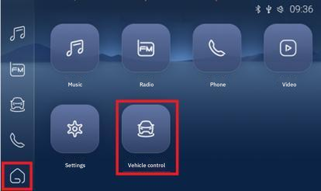
ENERGY RECOVERY MODE ON THE CENTRAL CONTROL SCREEN
- As shown in the picture above, click the [Vehicle Control] icon in the left navigation bar or drop-down menu on the car’s central control screen, and adjust it through [Driving - Energy Recovery Mode]. by selecting [Personalized Mode] in [Vehicle Control - Driving - Driving Mode], adjust it through the [Recycling Strength] slider.
- As shown in the picture above, click the main interface icon in the left navigation bar on the car’s central control screen to enter the main interface, click the [Vehicle Control] icon, and adjust through [Driving - Energy Recovery Mode].
Turn signal lights / hazard warning flashers
The turn signal / hazard warning flashers are used to confirm that the exterior turn signal or hazard warning flashers are working properly. If the green arrow does not flash when you turn or press the hazard warning button, check the fuse and bulb and replace if necessary.
Door ajar warning light
The warning light comes on when the front door is not closed or not closed tightly.
Tailgate open warning light
The warning light comes on when the tailgate is open or ajar.
Battery fault warning light
When the vehicle is powered on, the indicator light comes on. READY light should turn off after lighting up, indicating that the 12V battery is connected properly. If the indicator light is on at other times, it means that the 12V battery is discharged or there is a fault. Please charge the 12V battery first. If the following situations occur, please contact the nearest authorized repair service center to check the vehicle:
- The light does not illuminate when the vehicle is plugged in.
- It does not go out after lighting up.
- The warning light comes on, the “READY” indicator light goes out and the vehicle cannot drive.

Battery pack heating indicator light
When the vehicle is charging in a low-temperature environment, the battery pack heating indicator light will light up, indicating that the system is heating the battery to ensure that the battery is charged at a safe and reliable temperature. In low temperature environments, when the vehicle is fully charged and the charging power source is not disconnected, the battery pack heating indicator light also lights up, indicating that the system continues to heat the battery quickly to bring the battery to a more ideal temperature working environment. This light is a status indicator, not a fault light. It does not affect driving and will not illuminate while the vehicle is in motion. If it illuminates while the vehicle is in motion, please contact the nearest authorized service center.
Rear fog light indicator
Lights up when the rear fog lamps are on. Refer to “Rear fog lamps” in the Lighting chapter.
Headlamp high beam indicator
When the high beam headlights are on, the high beam indicator light comes on.

Position indicator light
When the small light is turned on, the indicator light comes on.
Anti-lock Braking System (ABS) Malfunction warning light
The ABS warning light illuminates when the vehicle is plugged in. This indicates the system is performing a self-check and the indicator light bulb is functioning properly. The warning light should go out after a few seconds. When the ABS warning light appears in the following situations, please consult the nearest authorized repair service center: the light does not illuminate when the power is turned on; the light does not go out; the light comes on while driving.
If the Anti-lock Braking System (ABS) warning light comes on while you are driving, indicating that your Anti-lock Braking System (ABS) There may be a malfunction. Although your vehicle may operate without the anti-lock brake system (ABS) function under normal conditions, but It is strongly recommended that you go to the nearest authorized service center as soon as possible to check the system and make necessary repairs.

EPS malfunction warning light
This warning light will illuminate momentarily when the vehicle is powered on. This indicates that the system is performing self-tests and the indicator light bulb is functioning properly. The light should turn off after a few seconds. When the electronic power steering (EPS) system detects a malfunction, the warning light will illuminate. When a steering system malfunction occurs, the vehicle can still be steered, but it requires considerable force. If the following situations occur, please consult your nearest authorized service center: the light does not illuminate when the vehicle is plugged in; it does not go out after lighting up; it lights up while driving.

Airbag malfunction warning light
When the vehicle is plugged in, the air bag warning light will illuminate for a few seconds and then turn off. This indicates that the indicator light bulb and the air bag system are functioning properly. When a malfunction occurs in the air bag system, the warning light indicates in one of the following ways:
- The lights do not illuminate when the vehicle is powered on.
- The lights remain on after being turned on.
- The lights flash or remain constantly on while driving.

Brake system / EBD warning light
When the vehicle is powered on, the brake system warning light will illuminate and go out after a few seconds (if the parking brake is released). This indicates that the indicator light is functioning properly. The brake system / EBD warning light will also illuminate when the parking brake is engaged. The light will go out when the parking brake is released. Always fully release the parking brake before driving the vehicle. If the brake system warning light illuminates when the parking brake is fully released, it may indicate that the brake fluid level in the reservoir is too low or there is a malfunction in the EBD system. To do this, follow these steps:
- Carefully pull out of the driveway and stop the vehicle.
- Check the brake fluid level.
- Add the recommended brake fluid to the MAX mark. Refer to “Adding Brake Fluid”.
- In the following situations, it is recommended that you drive your vehicle at a safe speed to the nearest authorized service center to check the brakes and confirm: • The brakes are working properly. • You can judge for yourself whether the car’s braking system is safe.
- In the following cases, we recommend that you tow your vehicle to the nearest authorized repair center for inspection and repair: • You discover a leak in your brake system. • The brake system warning light comes on continuously. • The brakes are not working properly.
Anti-theft system indicator light
The indicator light will illuminate when the door is unlocked and should go out when the vehicle is in high voltage state. This indicates that the indicator light is working properly.
Driver’s seat belt not fastened warning light
If the driver is not wearing a seat belt when the vehicle is powered on, the seat belt warning light will illuminate. Thereafter, unless the driver wears a seat belt, the following will occur: the seat belt warning light does not go off; when the speed exceeds 20 km/h, the warning light will flash and the warning buzzer will sound for a while.

Electronic parking brake system (EPB) Working indicator light *
When using electronic parking, the electronic parking system (EPB) working indicator light comes on, indicating that the vehicle is in the parking brake state. When the electronic parking brake is released, the indicator light goes out and the parking brake is released. This indicator light will illuminate as long as the electric parking brake is engaged. For a detailed introduction to the Electronic Parking Brake System (EPB), please refer to [Driving and Control - Electronic Parking Brake (EPB)*] contents.

Electronic Parking Brake (EPB) Malfunction warning light *
After the vehicle is powered on, the electronic parking brake system (EPB) fault warning light will light up for a few seconds and then go out, indicating that the warning light and the electronic parking brake system functional module are working properly. If there is a malfunction in the electronic parking brake system or the warning light itself, it will indicate in one of the following ways:
- The lights do not illuminate when the vehicle is powered on.
- They illuminate and remain on.
- They illuminate while the vehicle is in motion.
If the electronic parking brake system malfunctions, there is a risk of the vehicle rolling away.

Automatic Handicap Holding (AVH) Working indicator light *
When the automatic parking function is in effect and the vehicle is in parking state, the indicator light comes on. When the vehicle is out of park, the indicator light goes off. Automatic Handicap Holding (AVH) For a detailed introduction, please refer to the “Automatic Hold Function (AVH)*” in the “Driving and Handling” chapter.

Automatic Handicap Holding (AVH) Malfunction warning light *
When the automatic parking function module or the warning light itself fails, it will indicate in one of the following ways: The lights do not illuminate when the vehicle is powered on. The lights remain on after being turned on. The lights illuminate while the vehicle is in motion. If the above abnormalities occur, please contact the service center in time.
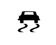
Electronic Stability Control (ESC) Malfunction warning light *
When the vehicle is powered on, the indicator light will light up briefly and then go out, indicating that the indicator light is working normally. During driving, if the ESC function is triggered, the ESC light will flash to inform the driver that ESC is working. If the ESC light is always on, it indicates an ESC fault, refer to the “Electronic Stability Control System (ESC)*” part in the “Ride and Handling” chapter.
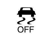
Electronic Stability Control System Off (ESC OFF) indicator light *
When the vehicle is powered on, the indicator light will light up briefly and then go out, indicating that the indicator light is working properly. When the “ESC OFF” switch is pressed, and the vehicle speed does not exceed the limit, some functions of ESC will be turned off, ESC The OFF light comes on. Refer to the “Electronic Stability Control System (ESC)*” part in the “Driving and Handling” chapter.
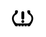
Tire Pressure Monitoring System (TPMS)
When the tire pressure is low, the indicator light flashes. When the tire pressure monitoring system fails, the indicator light flashes for a while and then stays on. Please check and adjust the tire pressure in time. The correct tyre pressure is detailed in the “Technical Data” chapter.
Indirect tire pressure monitoring system reset operation
For vehicles equipped with an indirect tire pressure monitoring system For vehicles with tires, tire pressure reset learning must be performed each time the tire pressure is adjusted or the tire is replaced. The steps are:
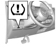
TIRE PRESSURE RESET SWITCH (7)
- The air pressure of the four wheels must first be adjusted to the specified value (see the “Vehicle Parameters” section for details).
- Press the reset switch (7) on the left side of the instrument panel for more than 2 seconds.
- The instrument displays “Tire pressure reset successful” to indicate that the reset operation is successful.

Low power battery warning light
When the vehicle is powered on, the warning light illuminates briefly and then turns off, indicating that the power battery charge is normal. If the light does not illuminate at this time, please consult an authorized repair service center. If the warning light comes on at other times, it means the power battery is low, please charge it in time.

Power battery thermal runaway warning light
If the warning light comes on, the car sounds a buzzer alarm, and the instrument panel displays the text “Vehicle failure, please leave the vehicle as soon as possible”, it means that the power battery is overheating and the vehicle is at risk of failure. Please pull over as soon as possible, get out of the vehicle immediately after it stops, evacuate to a safe area and call for help.
System fault warning light
This warning light comes on when the vehicle is powered on. The READY light should then go off, indicating the power system is functioning normally. If the following situations occur, please contact the nearest authorized repair service center to check the vehicle: The light does not illuminate when the vehicle is plugged in. ● Does not go out after lighting up. The warning light is on, the “READY” indicator light goes out and the vehicle cannot drive.

Vacuum pump fault warning light
When the vehicle is plugged in, the indicator light illuminates briefly and then turns off, indicating that the brake system’s vacuum pump is functioning normally. When a vacuum pump malfunctions, the warning light indicates in one of the following ways: does not illuminate when the vehicle is plugged in; lights up briefly and does not go out; Flashes while driving; does not turn off while driving. When the vacuum pump fails, the brake booster’s power will be reduced. You may feel that the brake pedal is stiff and you need to press the brake pedal harder to get braking force.

Drive power limit indicator
When the vehicle is powered on, the indicator light comes on. The READY light comes on and then goes off, indicating that the power system is normal. If the indicator light is always on or flashing, it indicates that the system has failed and the power performance will be limited. Please contact the authorized maintenance service center for repair as soon as possible.
Motor overheat warning light
When the vehicle is plugged in, the warning light illuminates briefly and then turns off, indicating that the motor temperature is normal. If the warning light comes on while driving, it means the motor temperature is too high. Please stop in a safe area as soon as possible to cool the motor. There are several situations where the motor may overheat:
- Long uphill climbs.
- Run at high speed for a long time.
- Frequent rapid acceleration.
- Driving long distances in hot weather.
Insulation warning light
When the vehicle is plugged in, the warning light illuminates briefly and then turns off, indicating that the warning light is normal. If the warning light comes on at other times, it means that the vehicle is in danger of electric leakage. Please contact the nearest authorized maintenance service center immediately to have the vehicle repaired.

Pedestrian alert system off indicator *
This indicator light comes on when the pedestrian alert system is off. For details on pedestrian warning devices, please refer to [Driving and Control - Driving Instructions - Pedestrian Warning Devices].
Reversing radar
The intelligent reversing radar uses an ultrasonic sensor installed on the rear bumper of the vehicle to determine the distance between the rear of the vehicle and obstacles when reversing.
- Self-check is normal: the vehicle is in READY state, shift into reverse gear, and depending on the vehicle configuration, the buzzer will sound once, or the instrument will not sound, which means the system is normal.
- Self-check fault: Put the car in reverse gear, and according to the vehicle configuration: (1) If the buzzer does not sound, it means that the rear left sensor is not working. If the buzzer sounds for about 2 seconds, it means that the rear right sensor is not working; (2) If the instrument panel sounds for about 2 seconds, the car model image on the central control screen displays the words “Please check the parking assist radar, you can drive normally”, and a yellow exclamation mark is displayed at the rear, it means that one or two sensors are not working. Every time the vehicle is in READY state and engaged in reverse gear, the intelligent reversing radar will enter the working state.
- Normal detection and beeping frequency: When the vehicle is approximately 1.5 meters to 1.0 meters away from the obstacle behind it, the buzzer or instrument emits a long intermittent warning sound, and the corresponding position behind the car model image on the central control screen (if equipped) displays green. When the vehicle is approximately 1.0m to 0.4m away from the obstacle behind it, the buzzer or instrument emits a rapid intermittent warning sound, and the corresponding position behind the car model image on the central control screen (if equipped) displays yellow. Within 0.4 meters of the obstacle behind it, the buzzer or meter will sound a long warning. When the sound is heard, the corresponding position behind the car model image on the central control screen (if equipped) will be displayed in red.
Reversing video display *

REVERSING GUIDE LINES: RED ~0.4 M, YELLOW ~1.0 M, GREEN ~2.0 M
As shown in the diagram, if the vehicle is equipped with a reversing camera, when the vehicle is in the READY state, the parking brake is released, and the vehicle is in reverse gear “R”, the rear view image and reversing guide lines will appear on the instrument panel.
Reversing Guide Lines: Based on the distance of objects from the rear of the vehicle, these guide lines are divided into three segments: red, yellow, and green. The bottom red line represents a warning line approximately 0.4 meters from the rear of the vehicle; the middle yellow line represents a warning line approximately 1.0 meter from the rear of the vehicle; and the top green line represents a warning line approximately 2.0 meters from the rear of the vehicle. The lines on the left and right sides represent the vehicle width.
Lighting
Exterior lighting
Light switch
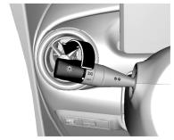
LIGHT SWITCH
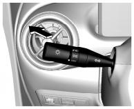
HIGH BEAM
After the vehicle is connected to the power supply, to turn the headlights on or off, turn the end of the combination switch lever. The light switch has 3 positions, each activating a different lighting function:
OFF = All lights are off.
- = The instrument panel, position lights and license plate lights are on. ≠○ = With the key switch (if equipped) in the ON position, the low beam headlights and all the above lights will illuminate.
High beam
To switch on high beam headlights: Make sure the key switch (if equipped) is in the ON position. Make sure the headlights are in low beam mode. As shown in the figure, push the combination switch lever toward the instrument panel. To switch the headlights from high beam to low beam, move the lever in the opposite direction until it returns to the normal position.
Headlamp flash
To flash the high beam headlights, pull the combination switch stalk toward the steering wheel and release it. The stalk will return to its normal position when released. The high beam headlights remain on until the lever is released.
Hazard warning light switch
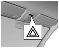
HAZARD WARNING LIGHT SWITCH
Press the button to turn the hazard warning flashers on or off.
Turn and lane change signals
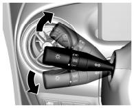
TURN AND LANE CHANGE SIGNALS
To activate the turn and lane change signals, the key switch (if equipped) must be in the ON position. Push up: right turn indicator. Push down: left turn indicator. At the end of the turn, the turn signal is automatically disengaged and the lever returns to its normal position. When changing lanes, move the joystick halfway (not all the way to the turn signal position) and hold it there. Release the joystick after changing lanes and it will automatically return to its normal position.
Rear fog lamp
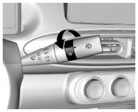
REAR FOG LAMP SWITCH
When the headlights are in low beam mode, turn the fog light switch on the wiper operating stalk to turn on the rear fog lights. When the rear fog lights are on, the rear fog light indicator on the instrument cluster lights up. To turn off the rear fog lights, turn the switch again.
Reversing lights
The reverse lights come on when the vehicle is plugged in and reverse gear is engaged.
Headlight leveling
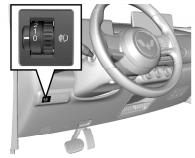
HEADLIGHT LEVELING KNOB
The headlight leveling knob is located on the left side of the vehicle’s dashboard. To adapt the headlight coverage to the vehicle load, to obtain the best possible lighting and to avoid distracting glare, turn the knob to the desired position:
0 = The front seat is occupied 1 = All seats are occupied 2 = All seats occupied and luggage compartment loaded 3 = The driver’s seat is occupied and the trunk is loaded
Accompany me home *
Depending on your vehicle configuration, your vehicle may be equipped with the Accompany Me Home feature, which provides lighting when you lock and leave the vehicle at night. Set it in the car’s central control screen [Vehicle Control - Lighting - Accompany Me Home]. The adjustable time length is: 15 seconds, 30 seconds, 60 seconds. With the Accompany Me Home function on the car computer, turn the lighting switch lever towards the steering wheel twice to trigger the delayed extinguishing function. 【Go Home with Me】 Function delay time (15 seconds, 30 seconds). If the car is not locked remotely, the low beam headlights will also turn off automatically after 10 minutes.
Light not turned off reminder
Depending on the vehicle configuration, if the key switch (if equipped) is in a non-ON position, or the vehicle is powered off, if the lighting switch is not turned to the OFF position, an audible prompt will sound when the driver’s door is opened. The alarm stops after the lights are turned off.
Interior lighting
Reading light
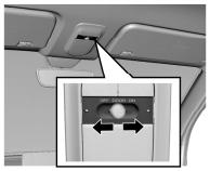
READING LIGHT
The front reading lights have 3 working positions:
ON: The light stays on until it is manually turned off. OFF: The light is off and does not come on even when the door is opened.
DOOR: The light comes on when any door (including the tailgate) is opened and goes off when all doors are closed.
Audio entertainment system
Audio Entertainment System Type I *
Button definitions and functions
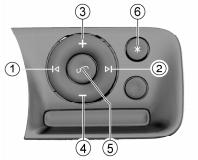
TYPE I CONTROL PANEL
| BUTTON NAME | KEY SEQUENCE NUMBER | BUTTON STATUS | MODE STATUS | ||
| RADIO MODE | USB MODE | BLUETOOTH MUSIC MODE | |||
| SRC | ⑥ | Short press | Can switch between FM, AM, USB, Bluetooth | ||
| Long press | Pause / Play | ||||
| VOL + (Volume +) | ③ | Short press | Volume increases in sequence | ||
| Long press | Volume Up | ||||
| VOL - (Volume -) | ④ | Short press | Volume down | ||
| Long press | Mute / Unmute | ||||
| Left button (previous song) | ① | Short press | Frequency Decrease / Automatic radio station search | Play previous track | |
| Long press | Manual descending adjustment | / | |||
| Right button (next song) | ② | Short press | Frequency Increasing / Automatic radio station search | Play next track | |
| Long press | Manual incremental tuning | / | |||
| Answer / end call | ⑤ | / | Short press to answer the call; Short press to enter private mode during a call / long press to hang up the call; When there is no incoming call, long press to dial the last dialed number. | ||
This section details the basic functions of the entertainment system host of this model. To fully enjoy the features of this unit and ensure long-term trouble-free use, please read it carefully and comply with the matters listed therein.
- Do not repair by yourself. If a fault occurs, please turn off the power immediately and go to a special after-sales service center for inspection. This machine is composed of many precise electronic components, which may be damaged or broken if disassembled or modified.
- Do not expose the machine to moisture, dust, steam, smoke, direct sunlight, etc.
- Do not use thinners or other chemical cleaners to contact the machine. Use a soft cloth to wipe off the dirt on the surface of the machine.
- Please keep this machine away from overheated or overcooled places.
- The operating temperature range of this machine is -30~80 ℃, Storage temperature range is -40~85 ℃.
- Avoid dropping or impacting the machine.
For safety reasons, please do not operate the entertainment system host while driving the vehicle. This section explains and illustrates the various operations of this model. Your vehicle may not be equipped with these functions. Please read according to the actual configuration of the model you purchased.
Basic Operations
Turn on the power — When powering on for the first time, press the key switch (ACC) Power on when turned on. Turn off the power — Directly turn off the key switch (ACC), You can turn off the radio. Mute — Long press the VOL- button to mute the sound; press any button again to cancel the mute and restore the volume to the level before the mute. Volume adjustment — Press VOL+, The volume increases to a maximum of 39; Press VOL- to decrease the volume to 0. Tip: When driving a car, please do not turn up the volume too high so that you can hear the sounds outside the car while driving. Mode Switching — Short press the mode key * to switch between FM, AM, USB and Bluetooth modes in sequence. Note: You cannot switch to USB mode when the USB flash drive is not inserted.
Listen to the radio
Automatic channel search
- Short press the right button to automatically search for radio frequencies from low to high. When a valid radio station is found, the search will stop and the radio will be played. If you short-press the left button again during the search process, the search will stop and the music will stay at the current frequency.
- After searching the entire band, if no valid radio station is found, the frequency before the search will be returned and played.
- The search process is muted and does not affect the search frequency.
- During the search process, press any valid key. Search stops. (Except volume button and answer / end button)
Manual channel search
- Press and hold the left or right button to enter step mode, and then you can manually adjust to the desired frequency and play.
- Short press the left button to reduce the manual search step size (FM: 100kHz,
AM: 9kHz) frequency and play it.
- Short press the right button to add a manual search step (FM: 100kHz, AM: 9kHz) frequency and play it.
- During the channel search process, the frequency displayed in the middle of the instrument interface changes synchronously with the search process.
Play USB
Play USB music — When ACC is turned on and the device is powered on, insert a USB drive with songs into the USB port and the device will automatically recognize and play them. Note: The maximum supported USB flash drive capacity is 64 GB.
Select Track — Short press the right button to play the next song. Short press the left button to play the previous song.
Supported playback formats — The audio formats supported by this device are: MP3 (32 kbps ~320 kbps), WMA (32 kbps ~320 kbps), AAC (32 kbps ~320 kbps). Support USB file system: USB file system supported by this machine: FAT16, FAT32.
Bluetooth functionality
When ACC is turned on and the device is powered on, connect your mobile phone to the Bluetooth of the device. The Bluetooth symbol will appear on the instrument display, and a prompt tone will sound when the connection is successful. Tip: Some phones may experience occasional pairing or connection issues due to compatibility issues or software installed on them. Please try again or use a different phone.
Select Track — Short press the right button to play the next song. Short press the left button to play the previous song.
Bluetooth phone
Bluetooth call answering — When a Bluetooth call is incoming, press the “Answer” button to answer the call; when a call is in progress, press the “End” button to hang up the call.
Mobile phone charging
This device supports mobile phone charging function and can provide 5V/1A charging power. The actual charging current is related to the status of the mobile phone. Next, connect the radio and the mobile phone with a USB charging cable to enter charging mode. Note: This player does not support mobile phones that require charging protocols. It only provides 5V/1A power to charge mobile phones in the form of a charger. The maximum current depends on the mobile phone itself.
The functions and operations of the audio and entertainment system may vary depending on the vehicle configuration.
Pre-repair inspection
When you feel that some functions in your car audio system are not working properly, please read the operating instructions carefully and check against the table below before sending it for repair. This will help you to eliminate the fault.
| PHENOMENON | POSSIBLE CAUSES AND SOLUTIONS |
| The host has no power (does not turn on) | 1. Please check whether the battery voltage on the vehicle is normal. The normal battery voltage should be between 9V and 16V. If it is lower or higher than this voltage, the host will not work properly. 2. If the car battery voltage is normal, please check whether the special fuse of the radio and cassette player assembly in the car has blown, and whether the power plug of the radio and cassette player assembly is loose or fallen off. 3. Please check whether the power cable of the radio and TV assembly in the vehicle is broken or short-circuited. |
| No sound from some speakers | 1. Please check whether the speaker cable is broken or short-circuited, whether the speaker plug is loose, and whether the speaker itself is damaged. |
| There is noise in the radio | 1. Check whether the radio antenna plug is loose or detached. 2. Is the car in a remote area with poor radio signal? 3. Is the car currently in an area with strong electromagnetic interference or near a transmission tower? |
| The volume can’t be turned up high | 1. Check whether the speaker output line is short-circuited to the ground. 2. Check if the cassette player assembly is too hot. This cassette player assembly has an automatic over-temperature protection function. In this case, turn off the machine and wait until the temperature drops before using it again. |
| PHENOMENON | POSSIBLE CAUSES AND SOLUTIONS |
| USB device cannot be recognized | 1. Replug the USB device or USB data cable. 2. Check whether the USB data cable or the device itself is damaged. 3. Format the USB device as FAT32 and load only MP3 / WMA music files. 4. The USB device is incompatible with the radio and TV assembly. Please replace it with a USB device of other models or specifications. |
| USB read takes too long | 1. Delete all files except MP3 / WMA music files in the USB device. 2. Appropriately reduce the number of music files in the USB device. 3. Use a USB device of another brand. |
If the fault still cannot be eliminated, please go to a special after-sales service center for inspection. Do not disassemble the host without authorization and repair it by yourself.
Audio Entertainment System Type II *
Safety Precautions
Thank you for purchasing this product! To ensure safe and correct use, please carefully read the following precautions.
- When driving, adjust the volume to a level where you can hear sounds outside the vehicle. If you cannot hear outside sounds while driving, it may lead to an accident.
- When operating the audio system while driving, please be fully aware of your surroundings and do not allow it to interfere with safe driving, otherwise it may cause an accident.
- Do not use this device for purposes other than vehicle use, as this may cause injury or electric shock.
- Do not continue to use the device if it is malfunctioning. If you detect smoke, unusual sounds, or an unusual odor, please immediately turn off the audio power.
- If the interior temperature of the vehicle is high, please allow it to cool down before use. Using this device at high temperatures may cause malfunction.
- Do not apply pressure to the screen, as this may cause malfunction.
- The driver should not operate this device while driving. If the driver wishes to operate the device, please be sure to pull over to a safe location first.
- While driving, the driver should not look at the screen of this device, otherwise they may overlook the situation ahead and cause a traffic accident.
- Do not use this device for extended periods before the vehicle is in READY mode, otherwise it will deplete the vehicle’s battery.
- Do not disassemble or modify this device, otherwise it may cause accidents, fires, or electric shocks.
- Do not use the device when it is malfunctioning, such as when it cannot display images or play audio, otherwise it may cause accidents, fires, or electric shocks.
- In case of any abnormal situations such as foreign objects entering, water splashing, smoke, or unpleasant odors, please stop using it immediately. Continued use may cause accidents, fires, or electric shocks.
Power On: Turn on the device. After the car’s logo is displayed, it will play the stored content.
Main menu and shortcut keys
Turn on the device and enter the main interface, then select the corresponding function. The main interface functions include multimedia, radio, and Bluetooth phone.
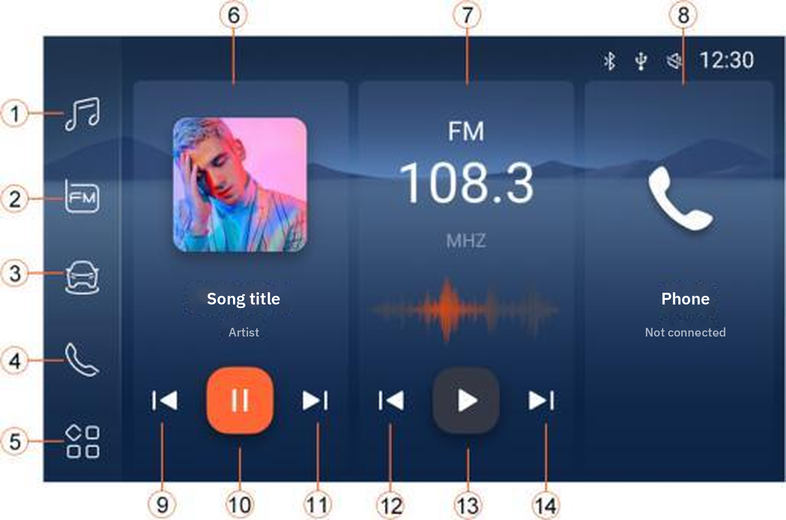
MAIN INTERFACE
- Click to enter the multimedia interface
- Click to enter the radio interface
- Click to enter the vehicle control interface
- Click to enter the Bluetooth phone interface
- Click on other interfaces to return to the home page, and click on the main interface to enter the full application interface
Click to enter the multimedia interface
- Click to enter the radio interface
- Click to enter the Bluetooth phone interface
- Music last song
- Music play / pause
- Next song
- Radio on
- Radio Play / Pause
- Next Radio
All applications
Click the button in the lower left corner of the main interface to enter this interface and select the corresponding function. The full application functions include music, radio, Bluetooth phone, USB video, system settings, vehicle controls.
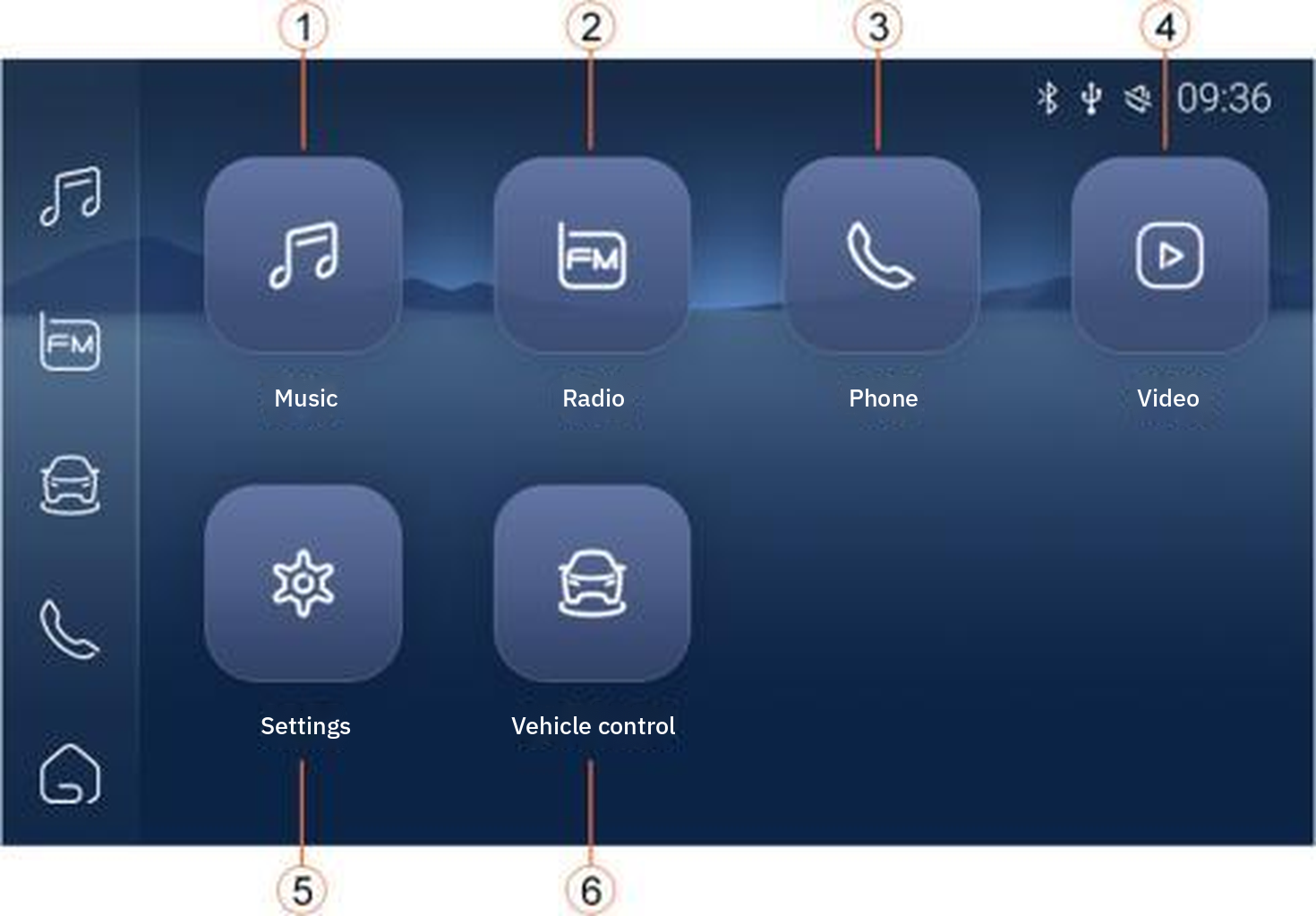
ALL APPLICATIONS
- Click to enter the multimedia music interface
- Click to enter the radio interface
- Click to enter the Bluetooth phone interface
- Click to enter the USB video interface (need to insert a valid USB first)
- Click to enter the system settings interface
- Click to enter the vehicle control interface
Drop-down menu page
The drop-down menu is used to quickly modify some system states (standby, turn on Bluetooth, turn off Bluetooth, adjust multimedia volume, adjust brightness, system settings, etc.).
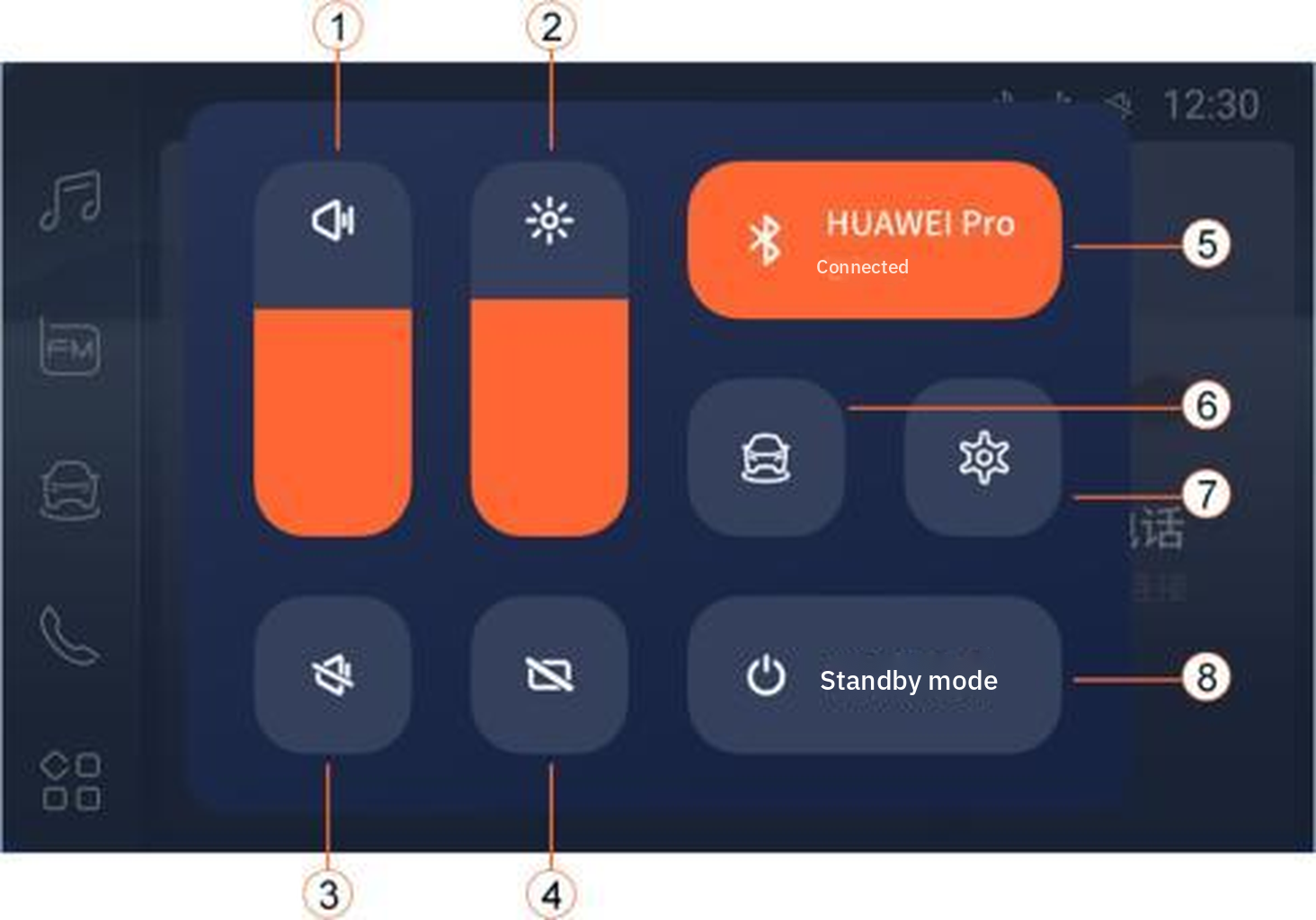
DROP-DOWN MENU
- Volume adjustment shortcut keys
- Brightness adjustment shortcut keys
- Mute shortcut key
- Screen off shortcut key
- Bluetooth shortcut switch, short press to turn on / off, long press to enter the Bluetooth settings interface
- Click to enter the vehicle settings shortcut key
- Click to enter the system settings shortcut key
- Click to enter standby mode
USB Music Mode
After inserting the USB device, the system automatically recognizes the insertion of the USB device, clicks to enter the USB music interface and automatically plays.
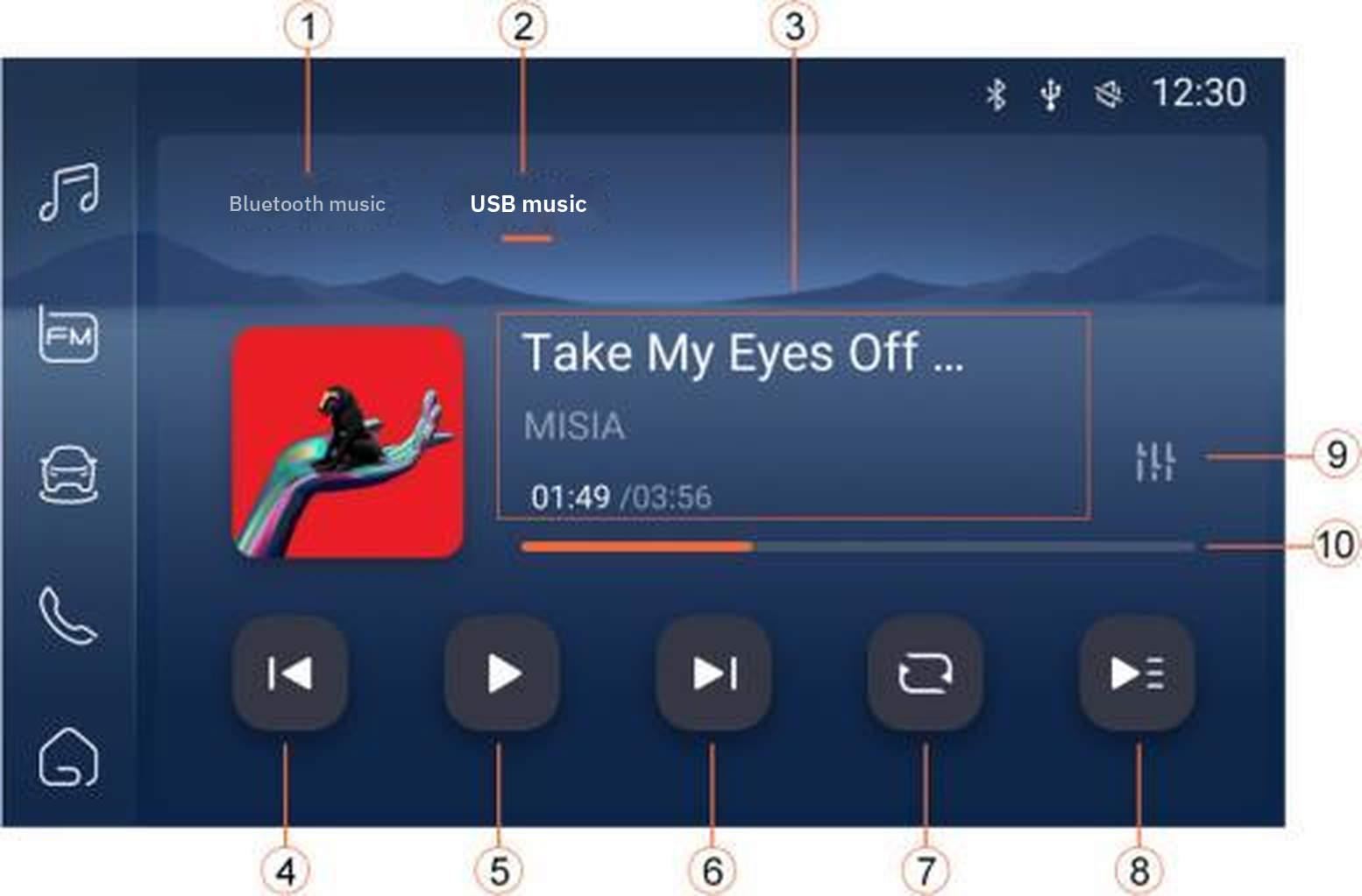
USB MUSIC MODE
- Click to enter the Bluetooth music interface
- Click to enter the USB music interface
- Current song information display
- Previous song
- Music play / pause
- Next song
- Play mode: Loop all => Single loop => Random play, default loop play (all loops)
- Playlist: Click to enter the playlist
- Click to enter the sound settings
- Song progress bar display
USB Video Mode
Insert the USB device, click the pop-up window to enter the folder, click the video file to play, or enter the full application and click the video icon, to play.
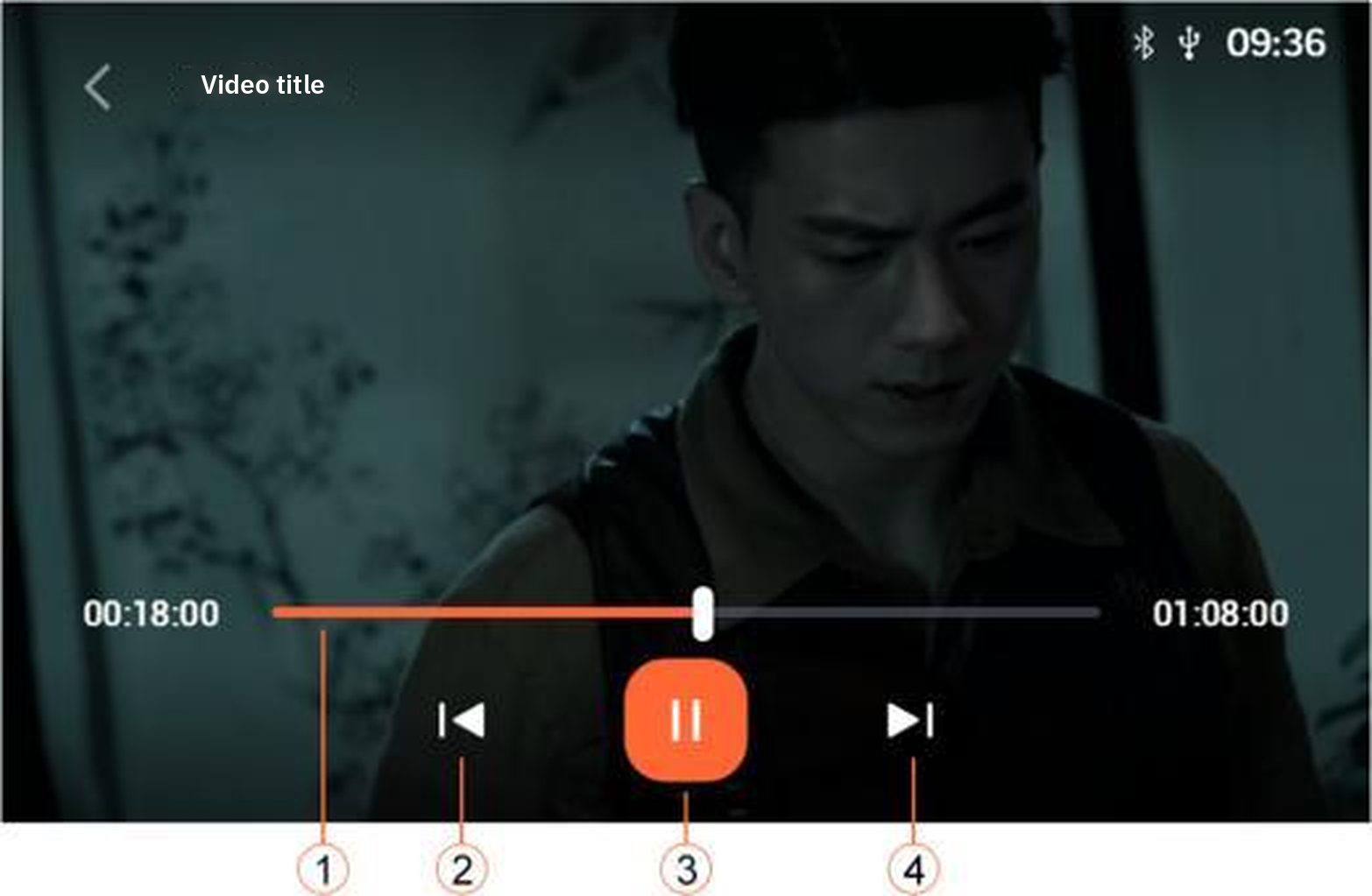
USB VIDEO MODE
- The current video playback progress bar is displayed
- Short press: previous video, long press: fast rewind
- Video play / pause
- Short press: download the next video, long press: fast forward
Radio
The radio status, including band, frequency, etc., is updated synchronously on the radio interface. The FM / AM band switch button shows the band currently being played. For example, if you are currently listening to an FM station, the band button “FM” is highlighted.
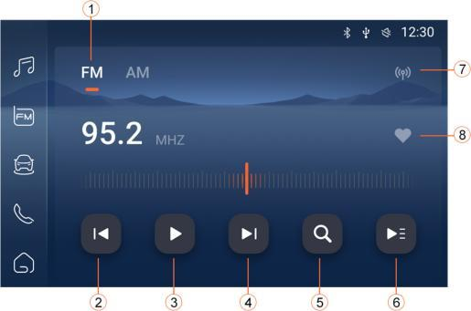
RADIO
- FM / AM switch button
- Radio the previous station
- Radio play / pause
- Select the next station
- Quick browsing: Start from the currently playing station and quickly browse, each valid station plays for 5 seconds until it returns to the original playing station.
- Click to enter the radio station list
- Search station: Start from the lowest frequency point and search the entire frequency band in one circle
- Add / Remove Radio Stations from Favorites
Bluetooth calling
There are three ways to enter the Bluetooth call interface: one is to click the phone card on the home page, the second is to click the phone icon in the left navigation bar, and the third is to click the phone icon in the full application interface.
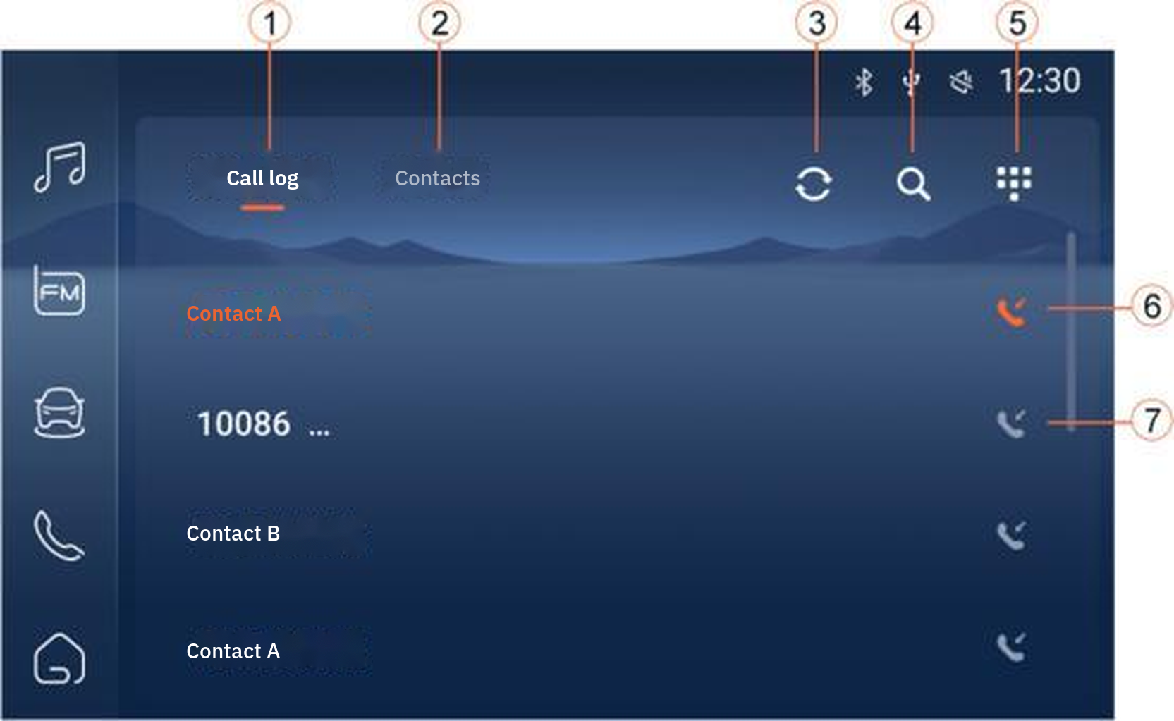
BLUETOOTH CALLING
- Call history of the currently connected phone
- Click to enter the address book interface
- Click to synchronize call logs and contacts
- Search for contact
- Click to enter the dial keyboard interface and make a call
- Missed calls
- Received calls
Bluetooth music
After connecting to Bluetooth, you can click the music icon in the left status bar or the full application interface to enter the Bluetooth music interface.
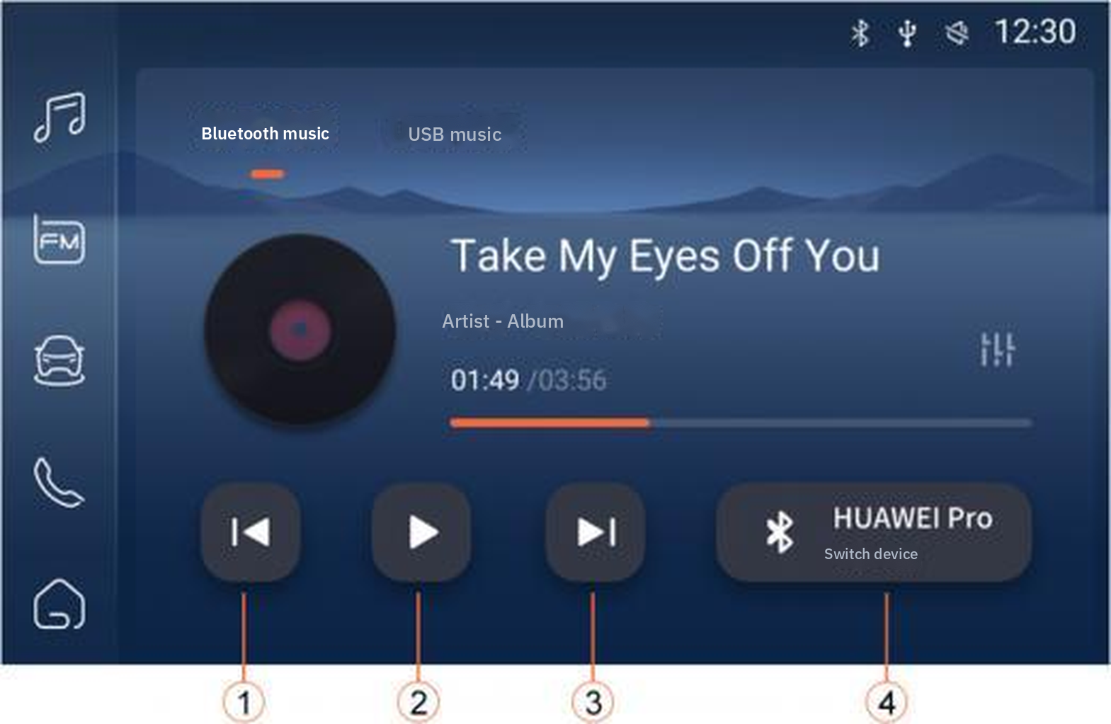
BLUETOOTH MUSIC
- Previous song
- Music play / pause
- Next song
- Click to enter the Bluetooth setting interface and switch to other Bluetooth
System Settings - Bluetooth
Click the drop-down menu or the full application settings icon to enter the Bluetooth settings interface.
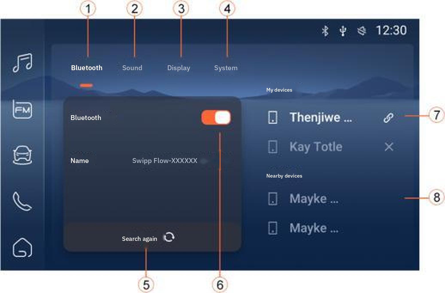
SYSTEM SETTINGS - BLUETOOTH
System Settings - Sound
Click the drop-down menu or the full application settings icon to enter the sound settings interface.
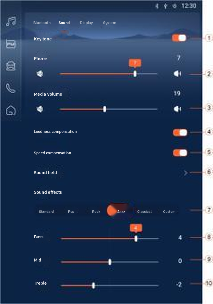
SYSTEM SETTINGS - SOUND
- Click to enter the Bluetooth settings interface
- Click to enter the sound settings interface
- Click to enter the display settings interface
- Click to enter the system settings interface
- Click to search for Bluetooth devices
- Bluetooth switch: On by default. When off, the search button will not be displayed.
- Display currently connected devices
- Nearby valid Bluetooth devices
- Key tone on / off
- Phone volume adjustment: 0~10
- Multimedia volume adjustment: 0~39
- Loudness compensation on / off
- Speed compensation on / off
- Click to enter the sound field adjustment interface
- Sound effect mode switch
- Bass adjustment: -7~7
- Mid-range adjustment: -7~7
- Treble adjustment: -7~7
System Settings - Display
Click the drop-down menu or the full application settings icon to enter the display settings interface.
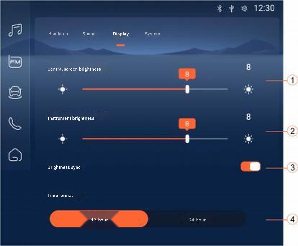
SYSTEM SETTINGS - DISPLAY
- Central control screen brightness setting: 1~10
- Instrument screen brightness setting: 1~10
- Brightness synchronization switch
- Time mode setting: 12-hour system and 24-hour system
System Settings - System
Click the drop-down menu or the full application settings icon to enter the system settings interface.
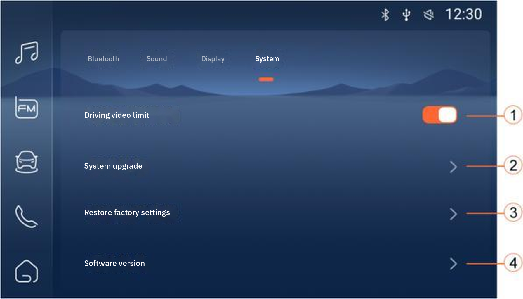
SYSTEM SETTINGS - SYSTEM
- Driving video limit on / off (when the vehicle speed exceeds 15 km/h, the video playback will be paused and a safety notice will be prompted)
- Click to enter the upgrade interface and upgrade the Bluetooth version
- Click Restore Factory Defaults
- Click to view the current software version information
Vehicle Control – Driving
Click the left navigation bar, drop-down menu, or the full-application vehicle control icon to enter the driving settings interface.
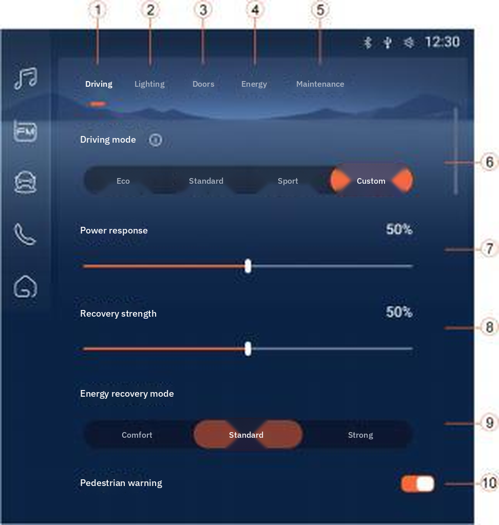
VEHICLE CONTROL – DRIVING
- Click to enter the driving settings interface
- Click to enter the lighting settings interface
- Click to enter the door and window settings interface
- Click to enter the energy settings interface
- Click to enter the vehicle maintenance settings interface
- Driving mode settings. When the personalized mode is selected, the power response and recovery intensity sliders will pop up for setting.
- Power response settings
- Recycling intensity setting
- Energy recovery mode setting
- Pedestrian warning switch
Vehicle Controls - Lighting
Click the left navigation bar, drop-down menu, or the full-application vehicle control icon to enter the lighting settings interface.
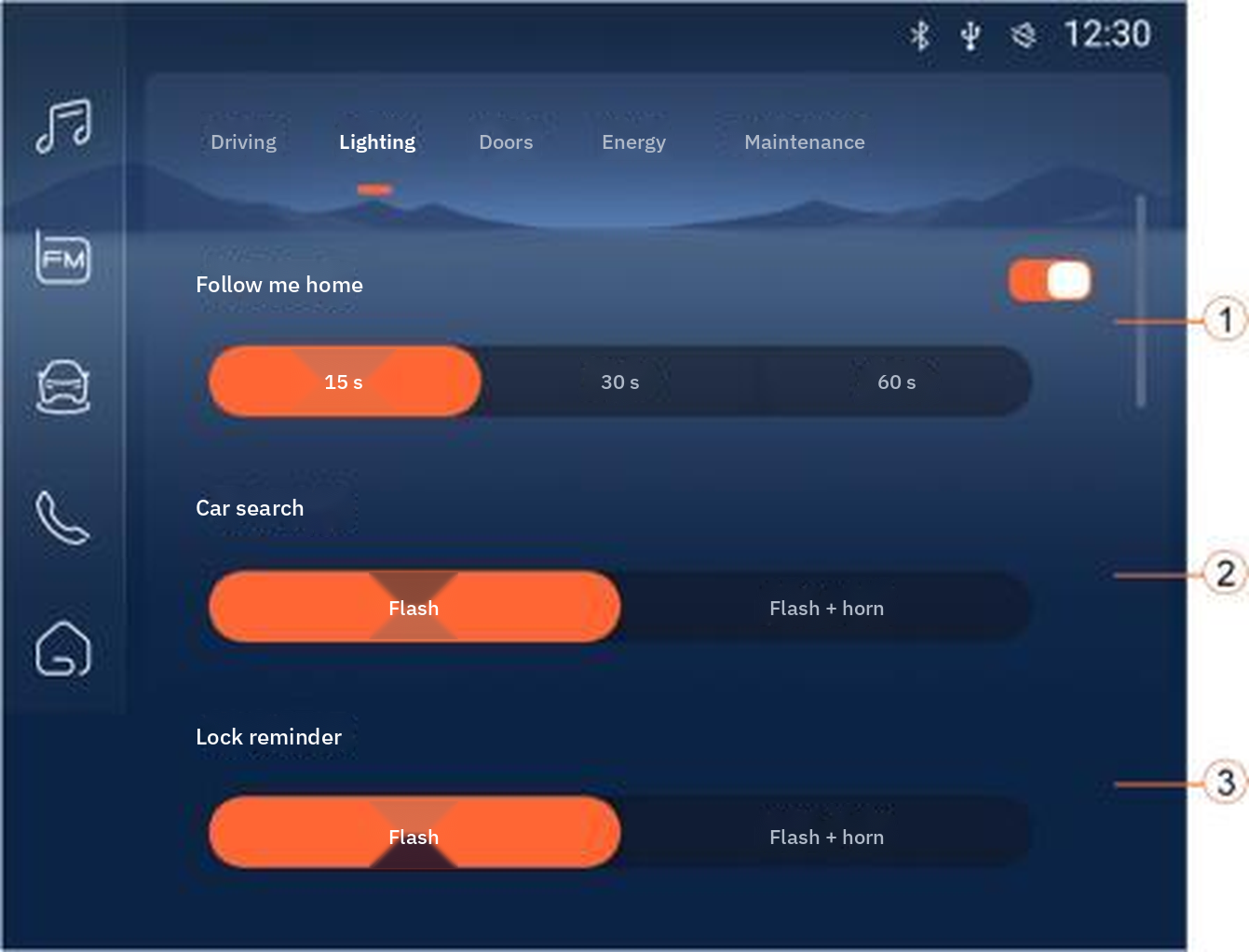
VEHICLE CONTROLS - LIGHTING
- Accompany me home switch and time selection
- Car search function settings
- Lock car reminder settings
- Wiper interval time setting
Vehicle Controls - Doors and Windows
Click the left navigation bar, drop-down menu, or the full-application vehicle control icon to enter the door and window settings interface.
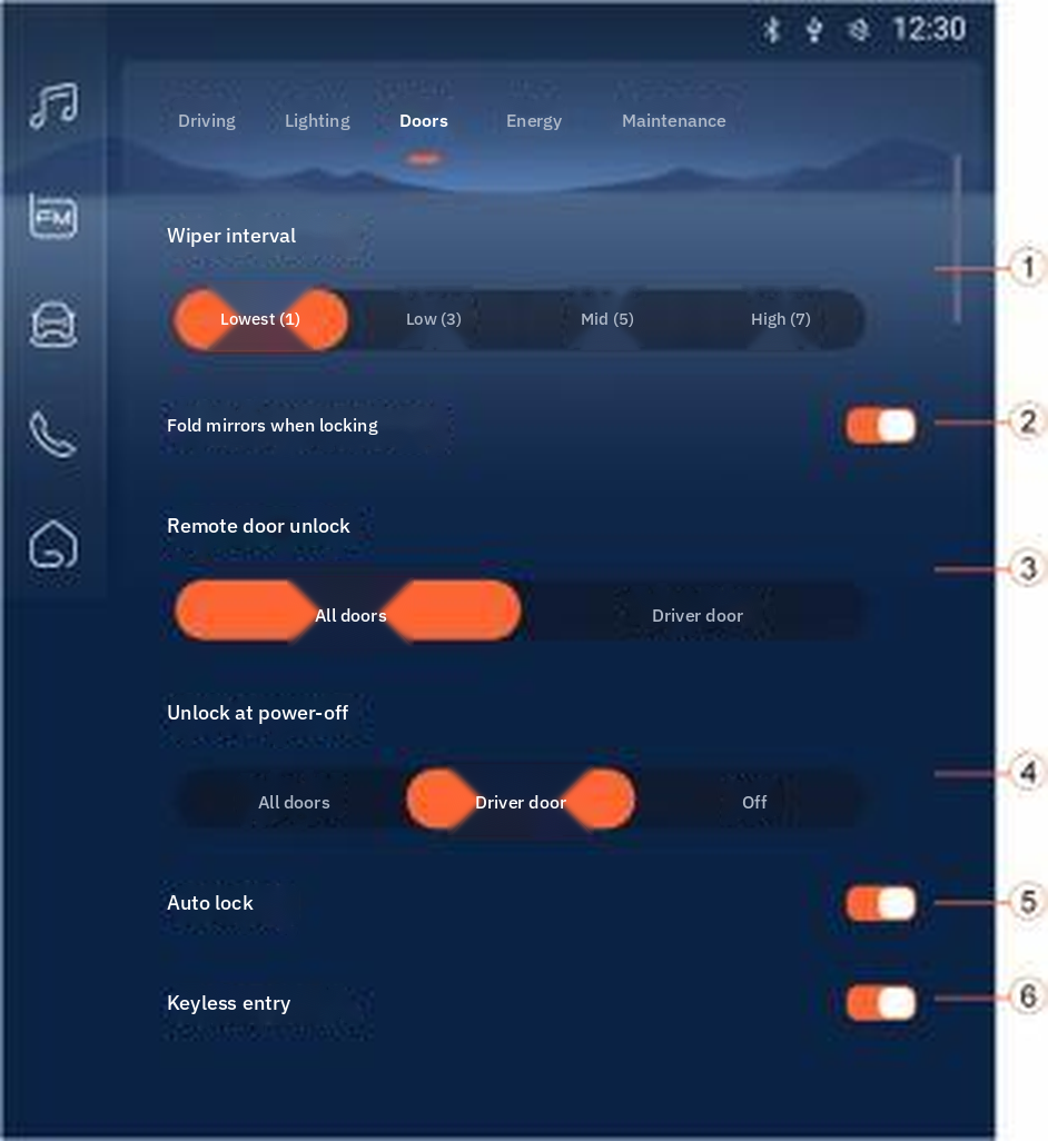
VEHICLE CONTROLS - DOORS AND WINDOWS
Vehicle Control - Energy
Click the left navigation bar, drop-down menu, or the full-application vehicle control icon to enter the energy settings interface.
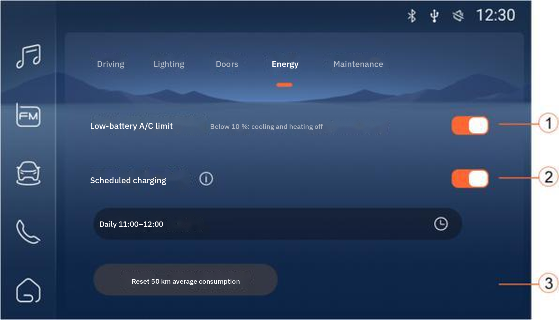
VEHICLE CONTROL - ENERGY
Vehicle Control - Vehicle Maintenance
Click the left navigation bar, drop-down menu, or the full-application vehicle control icon to enter the vehicle maintenance settings interface.
- Automatic folding rearview mirror switch when locking the car
- Remote door unlock settings
- Automatic unlocking when the engine is turned off
- Automatic locking switch
- Sensorless key entry switch
- Low battery air conditioning limit switch
- Switch on the scheduled charging function. Click the time icon to set the scheduled charging time.
- Reset button for the average energy consumption over the past 50 km
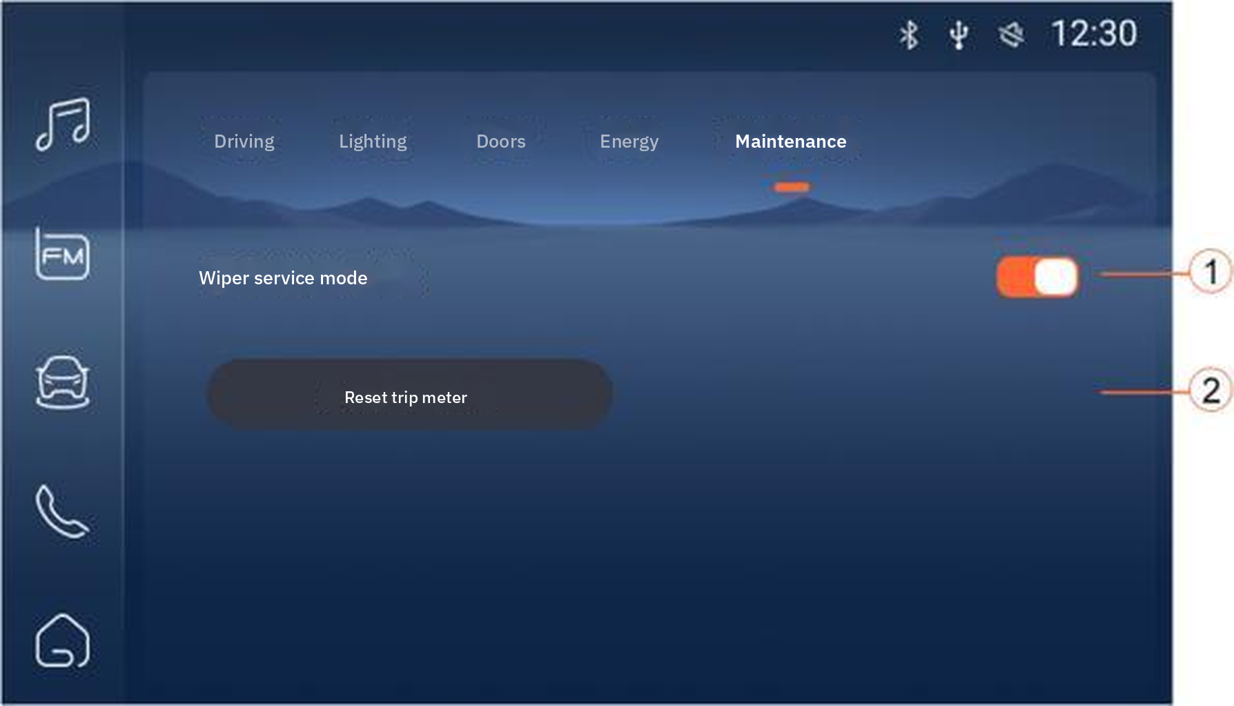
VEHICLE CONTROL - VEHICLE MAINTENANCE
- Wiper maintenance function switch
- Subtotal mileage reset button
Steering wheel buttons
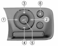
STEERING WHEEL BUTTONS
| BUTTON | RADIO SOURCE | USB AUDIO SOURCE | USB VIDEO | BLUETOOTH MUSIC | BLUETOOTH PHONE |
| ① Previous song | Short press: Previous (low frequency band) Long press: No response | Short press: Previous song Long press: No response | Short press: Previous song Long press: rewind | Short press: Previous song Long press: No response | No response |
| ② Next song | Short press: next station (high frequency band) Long press: no response | Short press: next song Long press: No response | Short press: next song Long press: Fast forward | Short press: next song Long press: No response | No response |
| ③ Volume + | Short press: Volume +1 Long press: Continue to increase | ||||
| ④ Volume- | Short press: Volume -1 Long press: Mute. Short press the “Volume +/-” button: Exit mute and restore the volume to the last value before mute | Short press: Volume -1. Long press: mute microphone, Fang can’t hear the sound. Short press “Volume +/-” Key: cancel mute mic, Restore to last static Volume value before microphone | |||
| ⑤ Answer / hang up | Short press on the incoming call interface to answer the call; Short press on the call interface to hang up the call; Long press on the incoming call interface to reject the call | ||||
| ⑥ Multi-function switch (press and hold for about 5 seconds to restart) | Local switching: switch to the next audio source (USB music - Bluetooth music - local radio) | Respond to long press function | |||
Temperature control system
Vents
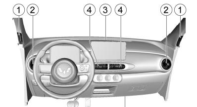
VENTS
- Front door window defrost vents
- Side vents
- Front windshield defrost vents
- Central vents
- Floor vents
Front door window defrost vents — The front door window defroster vents direct air toward the side windows, primarily near the exterior mirrors.
Side vents — to either side of the front passenger area or to the side windows via two adjustable side vents.
Windshield defroster vents — Directs air to the front windshield.
Central vents — You can control the direction of airflow from the center vents.
Floor vents — Floor vents direct air to the front footwell.
Ventilation mode
According to the desired airflow direction, rotate the mode selector knob. The ventilation mode can be selected into one of the following five positions:
Face Mode
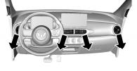
FACE MODE
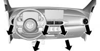
FACE / FEET MODE
This mode allows air to be delivered from the center vents and side vents.
Face / Feet Mode
This mode splits the air into two paths. Half of the air goes through the floor vents and the rest goes through the center and side vents.
Foot Mode
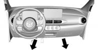
FOOT MODE
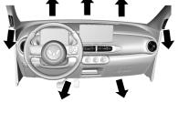
FOOT / DEFROST MODE
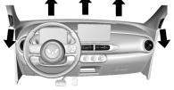
DEFROST MODE
Most of the air is drawn through the floor vents, with a smaller amount drawn through the windshield and front door window defroster vents, as well as the side vents.
Foot / Defrost Mode
This mode directs air through the front windshield defroster vents, front door defroster vents, and floor vents.
Defrost mode
This mode directs air through the front windshield defroster vents and the front door defroster vents.
Air conditioner
Air conditioning control panel
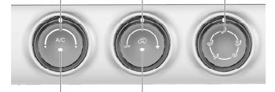
AIR CONDITIONING CONTROL PANEL
- Temperature control knob
- Fan control knob
- Ventilation mode assignment knob
- A/C button
- Inside and outside cycle key
Fan control knob
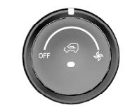
FAN CONTROL KNOB
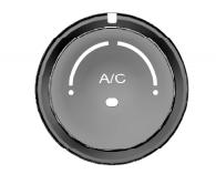
TEMPERATURE CONTROL DIAL
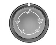
VENTILATION MODE ASSIGNMENT
KNOB
There are 4 air volume settings. Rotate the fan speed control knob to control the air volume of the system.
Temperature control dial
The temperature control knob is used to control the temperature of the air coming out of the vents. Turn the knob to the blue area for cool air and to the red area for warm air.
Ventilation mode assignment knob
According to the desired airflow direction, rotate the mode selection knob to select blowing face, blowing face / blowing feet, blowing Foot, Blow Foot / Defrost, Defrost and other modes. For details, please refer to the previous “Ventilation Vent - Ventilation Mode” content.

Air conditioning (A/C) button
Turn on the air conditioning system (A/C):
- The vehicle is in READY status.
- Press the air conditioner (A/C) button. The A/C button indicator light comes on, confirming that the air conditioner is working.
- Adjust the fan speed.
Turn off the air conditioner: A/C again Press the button to confirm that the air conditioner stops cooling. If the air conditioning system is on when the vehicle is powered off, it will turn on automatically the next time the vehicle is started.
Internal circulation mode button
Press this button when driving in dusty conditions, to prevent vehicle exhaust or outside fumes from entering the vehicle, or when quickly cooling or heating the passenger area. The indicator light will illuminate and the vehicle will recirculate air. Press the button again to switch to external recirculation mode, and the indicator light will go off. The system will remember the previously set air recirculation mode after restarting the vehicle. 20 minutes of operating the internal circulation mode, the car will automatically switch to the external circulation mode for a period of time to obtain fresh air. During this period, you may feel the heat or cold air outside the car entering the car.

Windshield defrosting
Used to select the front windshield defrost mode. Turn the fan knob to turn on the fan. The blower mode switches to the defrost mode, the A/C function is automatically turned on, and the indicator on the A/C button lights up. The air circulation mode is switched to external circulation.
Common air conditioning settings
The refrigeration unit of the air conditioning system cools the air inside the vehicle and removes moisture and dust. If the set temperature is high, even if the air conditioning cooling function (A/C) is turned on, Vehicles also generate heat.
Cool breeze
Rapid cooling — For quick cooling in hot weather and after a car has been exposed to the sun for a long time:
- Open the car window slightly to allow the heat inside the car to dissipate.
- Turn on the air conditioning (A/C).
- Turn on the internal circulation mode.
- Switch the air distribution mode to face mode (H).
- Adjust the temperature to the maximum setting for cool breeze.
- Turn the fan to maximum speed.
Normal cooling
- Turn on the air conditioning (A/C) button.
- Turn on the internal circulation mode.
- Switch the air distribution mode to face mode (H) or dual mode.
- Set the temperature to cool.
- Adjust the fan to the desired speed.
Warm air
Rapid heating — Use the Rapid Heat mode to quickly heat the passenger area. Do not use this mode for extended periods, as this can cause the air quality inside the vehicle to deteriorate and the windows to fog up. While clearing the windows, turn off the recirculation mode and allow fresh air to enter the vehicle. For maximum warm air:
- Turn on the internal circulation mode.
- Switch the air distribution mode to foot mode (2).
- Adjust the temperature to the maximum warm setting.
- Turn the fan to maximum speed.
Normal heating
- Start external circulation.
- Switch the air distribution mode to foot mode (2) or dual mode.
- Set the temperature to warm.
- Adjust the fan to the desired speed.
Ventilation
Dual Mode — For use in cool, sunny weather conditions. Directs warm air to the floor area and cool outside air to the upper body. To use this setting:
- Turn off the inner loop button.
- Switch the air distribution mode to dual mode.
- Adjust the temperature to the desired temperature.
- Adjust the fan to the desired speed.
ventilation — To direct air out of the center and side vents:
- Turn on external circulation mode.
- Switch the air distribution mode to face mode (H) or dual mode.
- Set the temperature to cool.
- Adjust the fan to the desired speed
Ride and handling
Driving Instructions
Vehicle Control
Do not coast with the power off. In this case many systems will not function (e.g. brake booster) Driving in this manner is dangerous to yourself and others.
pedal — To ensure unimpeded pedal travel, the floor mat in the pedal area must not be too thick and no objects should be placed in the pedal area.
Emergency measures
If a tire is punctured while driving
While driving, if one tire is punctured, hold the steering wheel tightly, control the driving direction, slow down slowly, turn on the hazard warning lights, lightly step on the brake pedal, and stop the vehicle in a safe area.
A breakdown occurred while driving
If a breakdown occurs while driving, turn on the hazard warning lights, slow down slowly, and stop the vehicle in a safe area on the side of the road. Place a warning triangle 50 meters behind the vehicle during the day and 100 meters behind the vehicle at night. Please comply with traffic regulations. After the inspection, send the vehicle to a specially authorized maintenance service center for inspection and repair. The triangle warning sign is placed under the passenger seat or is handed to you by the salesperson when the vehicle is delivered.
If the vehicle does not work
If the instrument cluster does not display anything when the vehicle is powered on, check whether the 12V battery is discharged. If the 12V battery is insufficient, the vehicle will not be able to complete the starting procedure, please charge the 12V battery.
Operations in heavy snow
Slow down when approaching corners, going uphill, or crossing bridges. Avoid parking on hard shoulders, as this will hinder snow removal.
Driving in water
In an emergency, passenger cars, new energy vehicles and HEV hybrid vehicles can drive through the deepest 200 mm of water, and the speed cannot exceed 10 km/h; trucks, SUVs can drive through water up to a depth of 300 mm, and the speed cannot exceed 10 km/h. When driving in flowing water, you should be more careful. When driving through water, you should maintain a low speed and strictly prohibit stopping. After driving through water, you should check as soon as possible to see whether the brakes, horns, vehicle lights, and power steering functions are intact.
Pedestrian warning device
Pure electric vehicles make less noise when driving, and the low-speed pedestrian warning system equipped on the vehicle can effectively serve as a warning to pedestrians. The warning system will activate when the vehicle is traveling at a speed of 0-25 km/h or reversing, and the vehicle’s pedestrian warning device will emit a warning sound.
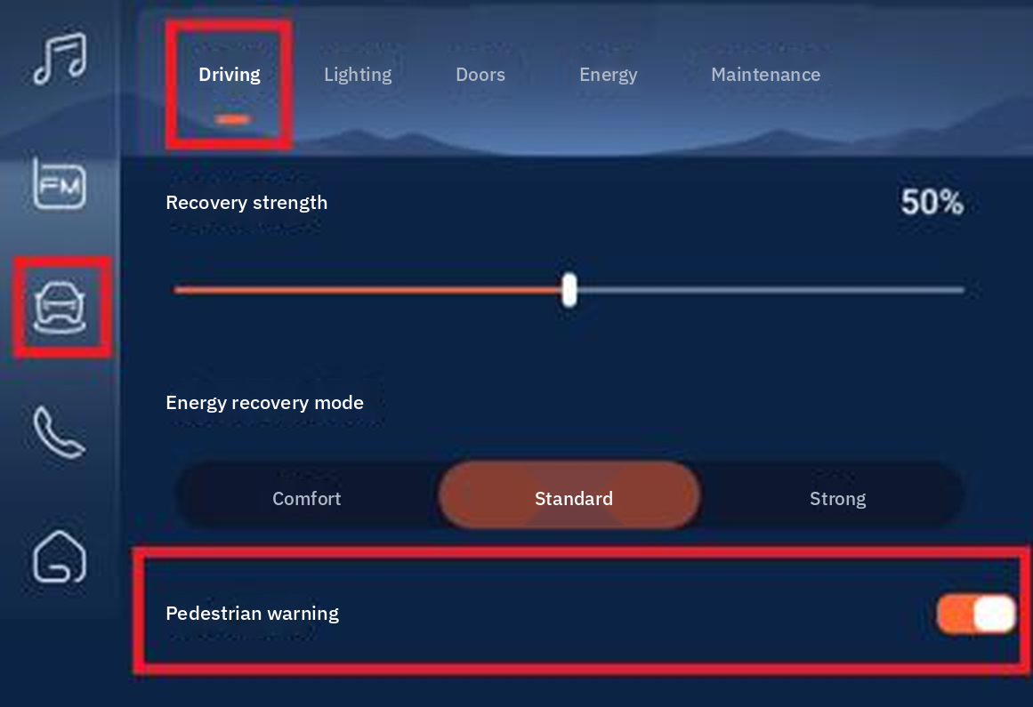
PEDESTRIAN WARNING SWITCH IN [VEHICLE CONTROL – DRIVING]
Depending on the configuration, some models can be equipped with a pedestrian warning device on the central control screen of the vehicle. Click the [Vehicle Control] icon in the left navigation bar, drop-down menu, or all applications on the central control screen to enter the [Driving] settings interface, where you can turn the pedestrian warning device on or off.
Vehicle Event Data Recording (EDR)
Your vehicle is equipped with an Event Data Recorder (EDR). The system can automatically record vehicle operation and safety system status information for a period of time before and after a specific event such as a vehicle collision (approximately 5 seconds before the accident and approximately 150 milliseconds after the accident). The system can effectively solve the current problems of difficulty in determining the cause of accidents and difficulty in identifying accident responsibilities, and provide effective support for road traffic accident work and just accident handling will help create a good and orderly road traffic environment.
Reading stored data
EDR data can be read by using a reading tool through the vehicle body OBD (on-board diagnostic system) interface, or by directly connecting to the EDR controller terminal (for example, when the vehicle body OBD interface is damaged, it is necessary to directly connect the reading tool to the EDR controller for reading). The data reading method may vary depending on the model or tool used. Please refer to the actual vehicle for details. The reading tool is provided by our parts manufacturer.
Description of the meaning and purpose of the recorded data items
The recorded data varies depending on the vehicle model or configuration. The configurations listed in the table are not available on all models. Please refer to the actual vehicle. The meaning and purpose of the recorded data items are described in the following table:
A data elements
| SERIAL NUMBER | NAME | WHAT THE DATA MEANS | DATA USAGE DESCRIPTION |
| 1 | Longitudinal delta-V | delta-V at a point on the vehicle in the X-axis direction | Used to determine changes in the vehicle’s longitudinal velocity |
| 2 | Maximum recorded vertical delta-V a | The maximum value of the cumulative change in vehicle speed in the X-axis direction | used in conjunction with the “Time to Maximum Recorded Longitudinal Delta-V” |
| 3 | Time to reach the maximum recorded longitudinal delta-V a | Along the X-axis, the time taken by EDR from time zero to the maximum value of the cumulative velocity change | used in conjunction with the “Maximum recorded longitudinal delta-V” |
| 4 | Clipping sign b | Indicates EDR acquisition acceleration (horizontal The time point when the sensor range is first reached (in the vertical direction, vertical direction) | Used to determine the time when the acceleration first reaches the sensor range |
| 5 | Vehicle speed | Wheel side linear speed or vehicle speed obtained by other means | Used to determine the vehicle speed at the time of collision |
| 6 | Service brake, on or off | Used to detect whether the driver has stepped on the brake pedal | Used to determine whether to brake when an accident occurs |
| 7 | Driver’s seat belt status | Status of the driver’s seat belt buckle switch | Used to determine whether the driver is wearing a seat belt |
| 8 | Accelerator pedal position, percentage of fully open position c, d | The percentage of the accelerator pedal’s actual position compared to the driver’s fully depressed position | whether the driver stepped on the accelerator pedal when the accident occurred |
| 9 | Revolutions per minute (rpm) d, e | The revolutions per minute of the vehicle engine’s main crankshaft | Used to judge the operating status of the engine |
| 10 | Power cycle in event | the first use of the ECU (Electronic Control Unit) that records EDR data The number of power cycles in the ECU that recorded the EDR data when the event occurred. | Used to record when an accident occurs EDR data: Number of ECU (Electronic Control Unit) power cycles |
| 11 | Power cycle when reading | From the ECU that records the EDR data Recorded from the first use to the time of reading Number of power cycles in the ECU from EDR data | Used to record when an accident occurs The number of power cycles of the ECU (Electronic Control Unit) when reading the EDR data |
| 12 | Event data record complete status | Is the event data fully recorded and stored in the record EDR? Data Status flags in the ECU | Used to determine whether the event is fully recorded |
| 13 | The time interval between this event and the previous event | If two events occur within 5 seconds, the time is the time from the start of event X to the start of event X-1 | Used to record the time interval between this event and the last event |
| 14 | Vehicle Identification Number | Number (VIN) assigned by the vehicle manufacturer | Used to identify vehicle production information |
| 15 | Record EDR ECU hardware number of the data | EDR in vehicles ECU with recording function, There may be more than one | Used to identify the ECU hardware number |
| 16 | Record EDR ECU serial number of the data | EDR in vehicles ECU with recording function, There may be more than one | Used to identify the ECU serial number |
| SERIAL NUMBER | NAME | WHAT THE DATA MEANS | DATA USAGE DESCRIPTION |
| 17 | Record EDR ECU software number of the data | EDR in vehicles ECU with recording function, There may be more than one | Used to identify the ECU software number |
B data elements
| SERIAL NUMBER | NAME | WHAT THE DATA MEANS | DATA USAGE DESCRIPTION |
| 1 | Longitudinal acceleration a | the vector acceleration of a point on the vehicle in the X-axis direction | Used to determine the longitudinal acceleration value |
| 2 | Lateral acceleration a, b | the vector acceleration of a point on the vehicle in the Y-axis direction | To determine the lateral acceleration value |
| 3 | Horizontal delta-V b | Y-axis component of the vector delta-V at a point on the vehicle | Used to determine changes in the vehicle’s lateral velocity |
| 4 | Maximum recorded horizontal delta-V b | The maximum value of the cumulative change in vehicle speed in the Y-axis direction recorded by the EDR | Used in conjunction with “Time to Maximum Recorded Lateral Delta-V” |
| 5 | The square of the maximum recorded sum delta-V b | The maximum value of the sum of the squares of the longitudinal delta-V and the transverse delta-V recorded by EDR | Used to determine changes in vehicle vector velocity |
| 6 | Time to reach maximum recorded lateral delta-V b | Along the Y-axis, the time taken by EDR from time zero to the maximum value of the cumulative velocity change | With “Maximum recorded horizontal delta-V” Use in combination |
| 7 | b to reach the maximum recorded total delta-V squared | The time from time zero to the occurrence of the maximum recorded sum delta-V squared | Used in conjunction with “the square of the maximum recorded sum delta-V” |
| 8 | Yaw angular velocity | Z-axis angle before and during the event, with clockwise being positive. | movement around the Z axis |
| 9 | Steering angle | The angular coordinate of the steering wheel, which has a value of zero. (0°) Indicates that the steering wheel is in the middle position (when driving in a straight line), and a positive value indicates that the steering wheel is turned counterclockwise (left) | driver’s steering intention and actual operation during driving |
| 10 | Tend | The end of the collision event. If this condition is not met until the end of the recording period, Tend can be defined as the time of the last recorded data point. | Used to determine the time when a collision occurs |
| 11 | Year c | Year the incident occurred | Record the time information of the event, which is obtained from the satellite positioning system to ensure the accuracy of the time |
| 12 | Month | Month the incident occurred | Record the time information of the event, which is obtained from the satellite positioning system to ensure the accuracy of the time |
| 13 | Sun c | Date the incident occurred | Record the time information of the event, which is obtained from the satellite positioning system to ensure the accuracy of the time |
| SERIAL NUMBER | NAME | WHAT THE DATA MEANS | DATA USAGE DESCRIPTION |
| 14 | Time c | Time of day the incident occurred (hours) | Record the time information of the event, which is obtained from the satellite positioning system to ensure the accuracy of the time |
| 15 | Points c | Time of day the incident occurred (minutes) | Record the time information of the event, which is obtained from the satellite positioning system to ensure the accuracy of the time |
| 16 | Seconds c | Time of day when the event occurred (seconds) | Record the time information of the event, which is obtained from the satellite positioning system to ensure the accuracy of the time |
| 17 | Gear | Actual gear | Record vehicle gear status |
| 18 | Engine throttle position, percentage of fully open position | The percentage of engine throttle valve opening | |
| 19 | Brake pedal position | Actual brake pedal position, from not pressed to fully pressed | braking behavior in a collision event |
| 20 | Parking system status | Used to detect whether the parking brake is activated | Determine the parking status on slopes and other road conditions |
| 21 | Turn signal switch status | used to indicate the vehicle’s intention to turn or change lanes | Reflects the driver’s steering intention |
| 22 | Driver seat belt pretensioner deployment time | from the event start point (T.) to the driver’s seat belt pretensioner deployment command | Record occupant protection system status information Information, to determine whether the vehicle can act promptly and accurately to effectively protect the passengers in the vehicle when a collision occurs, and to determine the effectiveness of the occupant protection system |
| 23 | Driver front airbag deployment time (first stage) | The time from the event start point (T.) to the first stage driver’s lower airbag deployment command | Record occupant protection system status information Information, to determine whether the vehicle can act promptly and accurately to effectively protect the passengers in the vehicle when a collision occurs, and to determine the effectiveness of the occupant protection system |
| 24 | Driver front airbag deployment time (second phase) | The time from the event start point (T.) to the second stage driver front air bag deployment command | Record occupant protection system status information Information, to determine whether the vehicle can act promptly and accurately to effectively protect the passengers in the vehicle when a collision occurs, and to determine the effectiveness of the occupant protection system |
| 25 | Driver side airbag deployment time | The time from the event start point (T.) to the side airbag deployment command | Record occupant protection system status information Information, to |
| SERIAL NUMBER | NAME | WHAT THE DATA MEANS | DATA USAGE DESCRIPTION |
| determine whether the vehicle can act promptly and accurately to effectively protect the passengers in the vehicle when a collision occurs, and to determine the effectiveness of the occupant protection system | |||
| 29 | Front passenger front airbag suppression status | Front passenger front airbag suppression status displayed | Record occupant protection system status information Information, to determine whether the vehicle can act promptly and accurately to effectively protect the passengers in the vehicle when a collision occurs, and to determine the effectiveness of the occupant protection system |
| 30 | Front passenger front airbag deployment time (first stage) | The time elapsed from the event start point (T.) to the first-stage front passenger front airbag deployment command | Record occupant protection system status information Information, to determine whether the vehicle can act promptly and accurately to effectively protect the passengers in the vehicle when a collision occurs, and to determine the effectiveness of the occupant protection system |
| 31 | Front passenger front airbag deployment time (second phase) | The time from the event start point (T.) to the second stage passenger front air bag deployment command | Record occupant protection system status information Information, to determine whether the vehicle can act promptly and accurately to effectively protect the passengers in the vehicle when a collision occurs, and to determine the effectiveness of the occupant protection system |
| 32 | Front passenger side airbag deployment time | from the event start point (T.) to the front passenger side airbag deployment command | Record occupant protection system status information Information, to determine whether the vehicle can act promptly and accurately to effectively protect the passengers in the vehicle when a collision occurs, and to determine the effectiveness of the occupant protection system |
| 33 | Front passenger side curtain airbag deployment time | from the event start point (T.) to the front passenger side curtain airbag deployment command | Record occupant protection system status information Information, to determine whether the vehicle can act promptly and accurately to effectively protect the passengers in the vehicle when a collision occurs, and to determine the effectiveness of the occupant protection system |
| 34 | Occupant protection system alarm status | Occupant protection system fault status | When a system alarm occurs, the driver should handle it promptly to |
| SERIAL NUMBER | NAME | WHAT THE DATA MEANS | DATA USAGE DESCRIPTION |
| eliminate the fault. Obstacles to avoid accidents | |||
| 35 | Tire pressure monitoring system alarm status | The vehicle’s tire pressure monitoring system detects low tire pressure in one or more tires. | When a system alarm occurs, the driver should handle it promptly to eliminate the fault. Obstacles to avoid accidents |
| 36 | Braking system alarm status | Braking system fault status, applicable to vehicles on the bus in this alarm state | When a system alarm occurs, the driver should handle it promptly to eliminate the fault. Obstacles to avoid accidents |
| 37 | Cruise control system status | Cruise control system operating status | Characterizes the status of the active safety system, used to determine whether the cruise control system is operating accurately and effectively |
| 38 | Adaptive cruise control system status | Adaptive cruise control system operating status | Characterizes the status of the active safety system, used to determine whether the adaptive cruise control system is operating accurately and effectively |
| 39 | Anti-lock braking system status e | Anti-lock braking system operating status | Characterizes the status of the active safety system, used to determine whether the anti-lock braking system is operating accurately and effectively |
| 40 | Automatic emergency braking system status e | Automatic emergency braking system operating status | Characterizes the status of the active safety system, used to determine whether the automatic emergency braking system is operating accurately and effectively |
| 41 | Electronic stability control system status e | Electronic stability control system operating status | Characterizes the status of active safety systems and is used to determine whether the electronic stability control system is operating accurately and effectively. |
| 42 | Traction control system status e | Traction control system operating status | Characterizes the status of the active safety system and is used to determine whether the traction control system is operating accurately and effectively. |
| 43 | Pre-event synchronization timing | T. Relative time from the last data sampling point to T. | Align other recorded data on the time axis to determine the sequence of each component’s actions and the driver’s operations |
Depending on the vehicle model or configuration, this function may not be equipped on all models. Please refer to the actual vehicle for details.
Startup and Operation
New car trial
Taking the following precautions within the first 500 km of driving can improve performance, increase vehicle economy and extend its life:
- Avoid sudden stops unless it is an emergency. This will allow the brakes to break in better.
- Try not to accelerate suddenly or drive at high speed continuously to avoid damaging the motor and save electricity.
- Do not use your vehicle to tow any other vehicle.
Power switch *
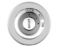
POWER SWITCH: LOCK / ACC / ON
Depending on the configuration, some models have a power switch located at the bottom right of the steering wheel, with the following working positions: LOCK, ACC (Electrical Accessories) and ON (On).
- LOCK — This position is used to turn off the power and lock the steering wheel. The key can only be removed by turning it to this position. To lock the steering wheel, remove the key and turn the steering wheel until it locks. If the key will not turn when you unlock the steering wheel, gently turn the steering wheel left or right while turning the key.
- ACC (Electrical Accessories) — This position connects the power supply to some electrical equipment, such as audio equipment. The meter starts to light up when the power is connected to this position. When the key is turned to the ACC position, check that the warning lights and indicator lights on the instrument cluster illuminate and extinguish normally.
- ON — turns on the power of all electrical accessories except high-voltage electrical appliances. vehicle can enter the READY state.
READY state (startup state)
READY state is reached, all high-voltage operating circuits are connected, the drive motor is ready for gear shifting, and the vehicle can be driven. The READY state is similar to the starting state of an internal combustion engine vehicle. Only when the vehicle reaches the READY state can it be engaged and driven, and the air conditioning system will provide cooling or heating.
How to enter the READY state:
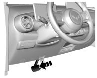
TYPE II: OPEN THE DRIVER’S DOOR, PRESS THE BRAKE PEDAL
Type I:
- Turn the power switch to ON position first;
- Then depress the brake pedal until the READY indicator light on the instrument cluster comes on. Once in READY state, the vehicle will remain in this state until you turn off the power switch to ACC or LOCK gear.
Type II:
- Unlock the vehicle with the remote control key, open the main driving door, the vehicle enters the high-voltage state, and the instrument cluster lights up.
- Press the brake pedal until the READY indicator on the instrument cluster lights up and the vehicle enters READY status.
How to exit the READY state:
Type I: Park the vehicle and turn the power switch to ACC or LOCK. Type II: Park the vehicle, open the driver’s door and unfasten the seat belt, the vehicle will exit the READY state and return to the high-voltage state. After exiting the READY state, the drive motor stops working and the vehicle cannot be driven in gear.
The vehicle exits READY and enters power-off state
- After getting out of the vehicle and closing the door, perform remote locking or remote locking (if equipped) and power off.
- Use the emergency power-off switch (if equipped). (For emergency use, please refer to the [Driving and Control - Brakes - Emergency Power Off Switch *] section for details on emergency power off.)
Preparation before entering the READY state:
- Check that the parking brake or electronic parking brake is engaged.
- Make sure there are no obstacles around the vehicle.
- Make sure all windows and lights are clean and transparent.
- Check tire condition, proper inflation pressure, and presence of foreign objects.
- Make sure the seat and rearview mirror are in the proper position and adjust them if necessary.
- Fasten your seatbelt and require passengers to do the same.
- Release the handbrake or electronic parking brake before starting the vehicle.
If you cannot enter the READY state
READY indicator light on the instrument cluster does not illuminate, the vehicle is not in the READY state. Please check whether the power switch (if equipped) is in the ON position or whether the brake pedal is depressed. If the instrument cluster displays nothing when the power switch (if equipped) is in ACC or ON, the 12V battery may be low on power and needs to be charged. We recommend that you contact an authorized repair center for assistance.
Emergency start *
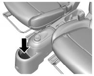
HOLD THE SMART KEY CLOSE TO THE STORAGE BOX ON THE AUXILIARY INSTRUMENT PANEL
If the battery of the smart key (if equipped) is low, the system may not be able to search for the key and may not start. Start the function: hold the smart key with the YT logo close to the storage box on the auxiliary instrument panel (as shown above) Press the brake pedal to put the vehicle into READY mode. If the vehicle cannot be unlocked due to insufficient power in the smart key, please refer to the [Keys, Doors and Windows - Door Locks] section first.
Parking
Before leaving the vehicle, select N gear, apply the parking brake, turn the power switch (if equipped) to LOCK gear, and remove the key; or select P gear, apply the electronic handbrake, and remove the key. Brake to complete parking.
When parking on a slope, apply the parking brake as firmly as possible and depress the brake pedal at the same time. When the vehicle is parked on an uphill slope, turn the front wheels away from the roadside. When the vehicle is parked on a downhill slope, turn the front wheels toward the roadside.
Creep function *
The creep function means that when the vehicle is in the D or R gear, without pressing the accelerator pedal or brake pedal and the parking brake or electronic parking brake is released, the vehicle will move at a lower speed in the gear direction until it reaches the specified maximum speed (7 km/h in D gear and 7 km/h in R gear. 4 km/h) The maximum speed during creeping is affected by factors such as terrain and load.
Shifting gears
Shift knob
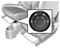
SHIFT KNOB (IMAGE FOR REFERENCE ONLY)
Turn the knob to change gears according to the markings on it. You can see the current gear in the gear display area on the instrument cluster. The background light of the corresponding gear on the knob will also light up. Only in the READY state can you shift gears and drive. When shifting into D or R gear, you must first step on the brake pedal, otherwise you cannot shift into gear. (The shift knob image is for reference only. The final appearance depends on the vehicle configuration and is subject to the actual vehicle.)
P: Park (if equipped) — Stop the vehicle and shift to P gear to park. R: Reverse gear — When reversing, shift into R gear. Before shifting gears, be sure to stop the vehicle completely and step on the brake pedal. N: Neutral — When the vehicle is in neutral, it neither moves forward nor backward. When the vehicle is stopped, put it in neutral. D: Forward gear — When driving forward, engage D gear and depress the brake pedal before engaging a gear. Release the parking brake before driving.
Gear shift — According to the vehicle configuration, the vehicle is in READY state. Next, turn on the power switch (if equipped) Turn the gear from ON to ACC. If the gear is in N, it will remain in N. If the gear is in R or D, it will switch to N.
Brakes
The braking system is designed to provide braking performance under a wide range of driving conditions. Braking reduces vehicle speed through friction between the brakes and the tires. Slight grinding and rubbing noises during braking are normal and require no special treatment. Occasional squealing during braking is also normal. This squealing can be caused by materials adhering to the friction surfaces during use, by prolonged periods of disuse, or by rusting after rain. As long as the squealing occurs infrequently, no special treatment is required. To avoid affecting pedal travel, do not lay thick carpet in the brake pedal area. If you find that the brake pedal does not return to its original position or the brake pedal travel becomes longer, it is strongly recommended that you have it checked by an authorized after-sales service center. This may indicate a malfunction in the brake system.
If the brakes temporarily lose their ability to stop due to overheating: Stop the vehicle in a safe area and wait for the brakes to cool. If the brakes temporarily lose their ability due to wet components, follow the steps below to help them restore normal performance:
- Check for vehicles behind you.
- Maintain a safe driving speed and ensure there is ample space behind and to the sides of your vehicle.
- Carefully apply the brakes until normal performance is restored.
Anti-lock braking system (ABS)
Anti-lock Braking System (ABS) It is an advanced electronic braking system that helps prevent the vehicle from sliding and losing control, and provides maximum braking ability on slippery roads. The ABS warning light illuminates briefly when the vehicle is powered on. If the ABS warning light persists or illuminates while driving, it indicates an ABS malfunction. Contact an authorized service center immediately. Refer to “ABS Malfunction Warning Light” in the “Instruments and Controls” section. During braking, the ABS system monitors the speed of each wheel. If one wheel shows a tendency to lock, the system will control the brakes of the two front wheels and the rear wheels respectively. The pedals will usually vibrate slightly and make noises. If the ABS warning light does not go out or lights up while driving, it is recommended that you go to a specially authorized repair service center as soon as possible to find out the cause of the fault.
Electronic Brake-force Distribution (EBD) *
EBD uses a high-speed computer to detect the moment of vehicle braking. During braking, the system senses and calculates the different surfaces to which the four tires adhere, deriving different friction values. This enables the four tires to brake in different ways and with different forces according to different situations, and continuously adjusts at high speed during movement, thus ensuring the stability and safety of the vehicle.
Electronic Stability Control (ESC) *
ESC OFF BUTTON ON THE LEFT OF THE INSTRUMENT PANEL
Automobile electronic stability control system is a new type of active safety system, which is an anti-lock braking system of automobile (ABS) and Traction Control System (TCS) function is further expanded. The system controls the driving force and braking force of the front and rear, left and right wheels through the ECU to ensure the lateral stability of the vehicle. The indicators related to the ESC system include ABS fault indicator light, EBD warning light, ESC warning light, ESC OFF indicator light.
- When the instrument is turned on, the self-check light will be on. All four lights will be on for 3 seconds, indicating that the ESC system is self-checking and the indicator light is working properly. Under normal circumstances, all four lights will go out after a few seconds. If there is a fault in the ESC system, only the ESC will be on after 3 seconds. The OFF light will go out and the other 3 lights will stay on.
- During driving, if the ESC function is triggered, the ESC light will flash to inform the user that ESC is working. If the ESC function is abnormal and the ABS + EBD function is normal, the ESC light will be on, indicating ESC failure. If ESC and ABS function abnormally, and EBD function normal, then ESC light and ABS light will be on. If ABS, EBD function is abnormal, the ESC light, ABS light, The EBD light is always on.
- ESC The OFF light is used to indicate that the ESC function is off (as long as the ESC function is off, this light will be on, and the function will be restored, this light will go out). If the user presses ESC OFF, some functions of ESC will be disabled. ESC OFF light is on. If the switch is pressed. If the user presses ESC again, the shutdown operation will not be performed immediately, but will be performed after the work is completed. If the ESC switch is pressed for more than 10 seconds, ESC will consider it as an incorrect operation (for example, the switch is accidentally pressed by something). The ESC function will not be turned off either.
- The ESC system is automatically activated every time the vehicle is restarted.
ESC function is on by default. If you need to turn it off, you can press the ESC OFF button on the left side of the instrument panel. The OFF button turns off the ESC function. After turning it off, the ESC OFF light is on. Press again to turn it on. It is not recommended to turn it off under normal circumstances. ESC only needs to be temporarily turned off when getting out of mud or climbing a snowy slope.
Parking brake
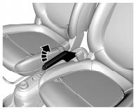
TYPE I: PARKING BRAKE LEVER
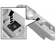
TYPE II: ELECTRONIC PARKING BRAKE SWITCH
The parking brake acts on the rear wheels. Depending on vehicle configuration, the parking brake lever or the electronic parking brake switch is located between the two front seats. To engage the parking brake, stop the vehicle and depress the brake pedal. Type I: Select N gear and tighten the parking brake lever; Type II: Select P gear and pull up the electronic parking brake switch.
To release the parking brake, Type I: Depress the brake pedal and: 1. Slightly pull up the parking brake lever. 2. Press the button on the head of the parking brake lever. 3. Release the parking brake lever while holding down the button. Type II: Depress the brake pedal, shift the gear to a position other than P, and press the electronic parking brake switch.
Electronic parking brake (EPB) *
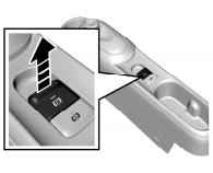
PULL UP: APPLY EPB
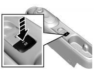
PRESS DOWN: RELEASE EPB
Manually applying / releasing the parking brake
- Manual parking — If you need to apply the parking brake, first step on the brake pedal to stop the vehicle, then pull up the electronic parking brake switch, the electronic parking brake working indicator light will light up, and the instrument cluster will display “electronic parking has been activated” and then release the switch. At this point, the electronic parking system’s brakes will engage, holding the vehicle in place.
- Manual release of parking brake — To manually release the parking brake, depress the brake pedal, shift to a position other than P, and press the electronic parking brake switch. The electronic parking brake indicator light will go out, and the instrument cluster will display “Electronic Parking Released,” indicating that the parking brake has been released.
Automatically apply / release the parking brake
- Automatic parking — When the vehicle stops, open the main driver’s door or turn off the vehicle, and the EPB caliper will automatically clamp the parking brake. In any gear (except N gear) in a stationary state, the vehicle will automatically apply the parking brake. You don’t need to pull the electronic parking brake switch.
- Automatic release parking — When you are ready to start, close the driver’s door, fasten the driver’s seat belt, step on the brake pedal, and the vehicle will enter the READY state. The gear is in D gear. When the car is in R gear, pressing the accelerator pedal will automatically release the parking brake.
When transporting, towing, or washing the vehicle, you may need to turn off the automatic clamping function of the EPB so that the vehicle can still be moved after exiting the READY state. How to turn it off: In the EPB released state, press and hold the EPB switch while pressing the emergency power-off switch to power off the vehicle. The vehicle will remain in the EPB released state after powering off.
Automatic Highway Holding (AVH) *
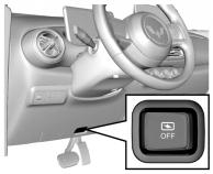
AUTOMATIC PARKING SWITCH
After turning on this function, the driver steps on the brake pedal to stop the vehicle or steps on the brake pedal when the vehicle is stationary. After releasing the brake pedal, the hydraulic pressure in the brake system will be maintained, so that the vehicle will be stopped in place, and you don’t need to pull the electronic parking brake to park the vehicle.
Automatic parking switch — When the vehicle is started (READY status), when the driver’s seat belt is fastened and the driver’s door is closed:
- In D gear, When you step on the brake in R gear on a steep slope, the automatic holding function will automatically turn on. (If you do not need this function, you can turn it off by pressing the AVH switch after AVH automatically turns on.)
- Or press the automatic parking switch to manually turn on the automatic parking function, and the background light on the switch will light up.
After this, the vehicle will automatically park when the following conditions are met:
- The vehicle stopped. 2. Press the brake pedal firmly. After the vehicle automatically parks, the automatic parking indicator light comes on. To start, press the brake, engage a gear, and lightly press the accelerator. Once the vehicle reaches the starting conditions, the parking brake will automatically release, allowing you to start smoothly. You can also manually release the parking brake by pressing the electronic parking brake switch after pressing the brake and engaging a gear. After the vehicle exits the automatic parking state, the automatic parking working indicator light goes out.
Emergency power off switch *
Some vehicles are equipped with an emergency power-off switch, which can be used when you need to cut off the vehicle’s power in an emergency. When the vehicle speed is below 2 km/h, pressing the emergency power-off switch will directly cut off the power. When the vehicle speed is ≥ 2 km/h, press and hold the emergency power-off switch for 5 seconds or press it three times within 2 seconds to power off the vehicle.
In an emergency, the vehicle can be restarted after using this function. The vehicle can be restarted after the following conditions are met: 1. The remote control key signal is valid. 2. Vehicle speed <2 km/h. 3. Press the brake pedal or open the driver’s door. The vehicle can enter the READY state from the high-pressure state when the following conditions are met: 1. The charging gun is not connected. 2. Depress the brake pedal or remote start (if equipped).
Electronic Power Steering (EPS)
Electronic Power Steering (EPS) The system provides steering assistance for the vehicle. This system does not require power steering fluid, which greatly facilitates daily vehicle maintenance. When the vehicle is powered on, the EPS warning light illuminates briefly. If the EPS warning light persists or illuminates while the vehicle is driving, it indicates a malfunction in the EPS system. In this case, visit a service center for inspection immediately.
If the electronic power steering system works under extreme conditions of long-term high-load operation, such as: the steering wheel is in the “fixed” position for a long time or the vehicle is repeatedly moved into the garage at a low speed and at a large angle, the thermal protection function may be triggered due to the excessive temperature of the electrical components. After entering the thermal protection state, the system will reduce the auxiliary Force, you need to use greater force to hit the square To restore normal power assistance, you can turn the steering wheel at a smaller angle or increase the speed, and restart the vehicle if necessary.
Charging specifications
How to determine if a vehicle needs charging
- If conditions permit, it is recommended that you charge your vehicle while it is parked. Shallow charging and discharging of the battery will help extend its lifespan. Do not wait until the battery is completely depleted before charging, as this may affect your next trip and shorten the battery lifespan.
- If the low battery warning light comes on while the vehicle is driving, it indicates that the power battery pack is low on power and the discharge capacity of the power battery is greatly reduced. At this time, please try not to drive on the highway or climb on the elevated road, etc., and charge as soon as possible.
- When the power gauge shows that the remaining power is low, or the cruising range cannot meet travel needs, it is necessary to charge.
Charging diagram
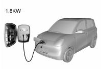
1.8 KW CHARGING
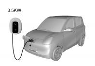
3.5 KW CHARGING PILE
Charging time
The on-board charger of this vehicle is 3.3 KW. The charger uses a standard household 220V AC power source. The charging power is related to the specifications of the charging gun / pile. (Note: If the external power source power differs from the rated power of the charger, the charging power will be the smaller one.) See the table below for specific parameters:
| CONFIGURATION | TIME | |
| SOC 20%-100% charging time (at room temperature) | Smart charging socket or standard AC charging cable (10A) | 8.8~9.2 hours |
| Original 3.5 KW charging pile (contact an authorized service center for installation) | 4.5~4.8 hours | |
| 7 kW charging station | 4.5~4.8 hours | |
| 30%-80% Charging time (at room temperature) | DC fast charging * | About 35 minutes (at room temperature, 20 KW or above Charging equipment) |
Check before charging
- Check that the parking brake or electronic parking brake is engaged. Depending on the vehicle configuration, place the key in the LOCK position (if equipped) or remove the key.
- Do not ride in the vehicle while charging. Ensure ventilation in the charging area and do not charge in a confined or narrow space.
- Before charging, check the surface and casing of the charging cable for damage. If so, contact a service center for repair or replacement. Ensure the charging cable is in a naturally extended state and do not allow it to hang in the air.
- Appropriate protective measures should be taken during the charging process to prevent children and other non-related personnel from approaching the charging vehicle and charging cable.
- When charging, please make sure there is no residual rainwater in the charging socket of the vehicle body and the surrounding area.
- Do not charge in rain, snow, standing water, or near fire, and do not charge during thunderstorms. If you encounter rain, snow, flooding, or strong winds while charging, stop charging and remove the charging cable. Otherwise, there is a risk of electric leakage.
- If the area near the charging port gets wet during charging, please unplug the charging plug from the power socket first while ensuring safety, and then unplug the charging gun from the charging port. If necessary, please use insulating gloves and contact the service center as soon as possible for inspection and confirmation.
- When touching the charging plug, please keep your hands dry and use insulating gloves if necessary.
- The recommended ambient temperature for charging is between 0 °C and 35 °C. Avoid charging in low or high temperatures (it is recommended to charge at noon in winter and in the morning and evening in summer). Try to avoid charging in high temperature environments such as direct sunlight. If the vehicle is equipped with a power battery heating system, during charging, if the internal temperature of the power battery is below 0 °C, The power battery system will automatically heat up first, and then charge the power battery pack after heating is completed.
- The charging plug is a high-voltage device and is strictly prohibited for use by children. Children are strictly prohibited from operating the charging process. If the charging area is frequented by children or people, safety signs should be posted.
- Lock the doors before leaving the vehicle to prevent theft.
Precautions
- To extend the service life of the power battery pack and ensure driving safety, try to avoid driving when the battery power is too low (<10%).
- Do not use the vehicle’s power battery pack for other purposes.
- Improper handling of the power battery may cause serious accidents, resulting in damage to the power battery or personal injury. To avoid accidents, please pay attention to the following matters:
- Do not expose the vehicle to an environment above 45 °C for more than 24 hours. Place the vehicle in a cool environment in time.
- Do not leave the vehicle in an environment of -25 °C for more than 7 days. Move the vehicle to a warmer environment immediately. If the vehicle is exposed to extremely low temperatures (below -25 °C) for a long time, the power battery pack may freeze, preventing it from charging and providing power to the vehicle, which is very dangerous.
- To increase the battery life and safety, we recommend that you:
- Vehicles without a power battery heating system will not be able to charge when the internal temperature of the power battery is below 0 °C. When the ambient temperature is low, please charge the vehicle as soon as possible within 1 hour after parking. If the vehicle cannot be charged due to low power battery temperature, please move the vehicle to a warm place or drive for a while before charging.
- When the vehicle is parked for a long time (more than 1 month), Please charge the battery to about 60% and disconnect the negative terminal of the 12V battery in the front compartment.
- Please try to avoid sudden acceleration and deceleration while driving.
Charging operations and precautions
Preparation :
- Stop the vehicle and turn off the power switch (if equipped). Parking is completed.
- Take out the charging cable from the luggage compartment and check whether the cable is intact.
AC charging operation :
1. Open the vehicle charging port
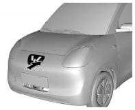
PRESS THE RIGHT SIDE OF THE CHARGING PORT COVER
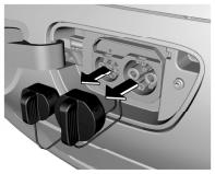
OPEN THE CHARGING PORT PROTECTIVE COVER
As shown in the figure, press the right side of the charging port cover to open it. As shown in the figure, open the corresponding charging port protective cover.
2. Insert the plug into the power socket
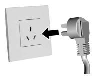
INSERT THE PLUG INTO THE SOCKET
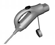
TAKE OUT THE CHARGING GUN, OPEN THE GUN COVER
Insert the plug into the socket. Take out the charging gun and open the charging gun cover. Please refer to the actual product for the specific charging gun.
3. Insert the charging gun into the vehicle charging port
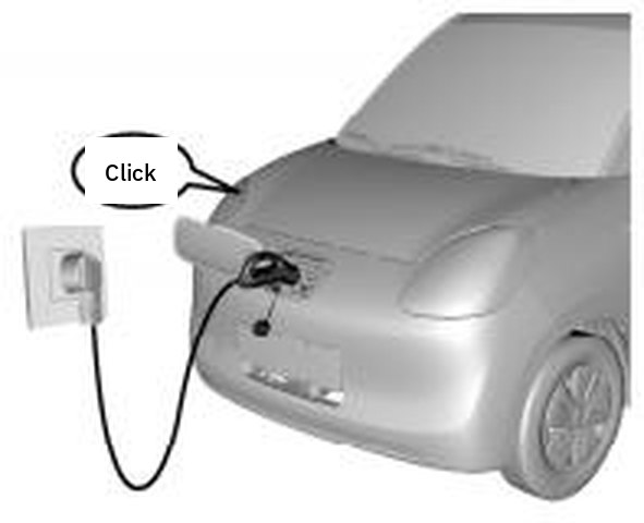
INSERT UNTIL YOU HEAR A “CLICK”
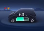
INSTRUMENT DISPLAY DURING
CHARGING
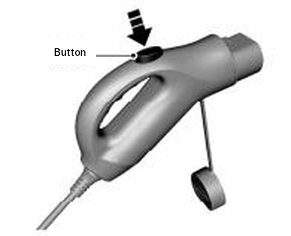
PRESS THE BUTTON TO PULL OUT
THE GUN
Insert the charging gun into the charging port until you hear a “click” sound.
The charging gun indicator light shows: Initial state: The indicator light flashes blue - green - blue - red for 1 second and then turns off. Waiting for connection, the blue light is always on. The gun is inserted normally and the blue light flashes. Charging, green light flashing. If a fault occurs, the red light will be on or flashing. When charging is complete, the green light will be on.
Instrument display interface during charging — Displays “Charging” and the current battery percentage, charging connection icon and charging status icon.
4. Charging is complete and then pull out the charging gun
After charging is complete, press the button to pull out the charging gun and close the charging gun cover. Replace the charging port cover and close the charging port. Please refer to the actual charging gun for details.
DC fast charging *
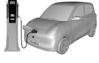
DC FAST CHARGING
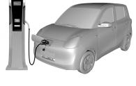
CHARGING STATION
When performing DC charging, please follow the operating instructions of the charging equipment, or charge under the guidance of the charging station staff.
Charging precautions :
- Park the vehicle in a ventilated place and do not let people stay in the vehicle.
- When charging, if there is a power outage, the charging system will continue to charge the vehicle when the power comes back.
- When charging, do not use false grounding devices such as grounding plugs. Such devices may pose a safety hazard of electric shock to personnel during charging.
- Before driving, make sure the charging gun is unplugged, the charging cable is stored, and the charging port cover is closed.
- The full charge time may vary slightly depending on the battery capacity, vehicle charge level, ambient temperature, external charging equipment, and onboard charger power. This is normal. When the ambient temperature is low, charging efficiency decreases and charging time is longer. The recommended ambient temperature for charging is between 0 °C and 35 °C. Avoid charging in low or high temperatures (recommended charging at noon in winter and in the morning and evening in summer). Try to avoid charging in high temperature environments such as direct sunlight.
- The full charge time may vary slightly depending on the ambient temperature and power level, which is normal. When the ambient temperature is low, the charging efficiency is reduced and the charging time is longer.
- If the vehicle is equipped with a power battery heating function During the charging process, the internal temperature of the power battery is below 0 ℃, The power battery system automatically heats the battery pack before charging. Vehicles without power battery heating will not charge if the internal power battery temperature falls below 0°C. Move the vehicle to a warmer location or drive it for a while until the battery temperature rises before charging.
Vehicle maintenance
General information
Accessories and vehicle modifications
We recommend using genuine spare parts and parts approved by our company that are specifically suitable for this vehicle. We cannot guarantee that other products will be compatible with this vehicle. even if these products meet specified requirements or are otherwise approved. Do not make any modifications to the electrical system without the approval of MCrown Auto.
Power battery recycling
If you need to replace the power battery, please be sure to hand over the old battery to the recycling service outlet designated by MCrown Auto for recycling. Discarding the power battery will pollute the environment and even cause personal injury. Relevant laws and regulations also require that this type of waste be recycled. For specific recycling details, please visit the official website or consult your local repair service center.
Vehicle Storage
Long-term storage — If the vehicle is to be stored for several months:
- Wash and wax the vehicle.
- Inspect the wax layer on the front compartment and underbody.
- Clean and protect the rubber seals.
- Drain the washer fluid reservoir.
- Adjust the tire pressure to the recommended full-load value.
- Charge the battery to approximately 60%.
- Park the vehicle in a dry, well-ventilated area.
- Check that the handbrake or electronic parking brake is engaged and the vehicle will not move on its own.
- Close all doors and lock the vehicle.
- Disconnect the clamp from the negative terminal of the vehicle’s 12V battery. Note that all systems will be disabled at this time, such as the anti-theft alarm system.
When the vehicle is to be put back into use:
- Connect the clamp to the negative terminal of the vehicle’s 12V battery. Activate the electronic devices for power windows (if equipped).
- Check the tire pressure.
- Refill the washer fluid reservoir.
- Check the battery charge and fully charge the battery before putting the vehicle back into use.
Driver’s Checklist
Regularly inspect the interior, exterior, and front compartment of the vehicle to maintain its safety and reliability.
Exterior
Tires — Properly inflated. (See “Wheels and Tires” in this section). No cracks in the sidewalls and treads. No foreign objects in the treads.
Lights — All daytime running lights, headlights, taillights, turn signals, brake lights, and fog lights.
Fuel Reservoirs — Check that the fluid levels in all reservoirs under the hood are appropriate.
Windshield Wipers — Check the condition of the wiper arms and blades.
Interior
Steering — Check that the steering wheel is not too loose (free play).
Parking Brake — Ensure the parking brake lever (if equipped) has proper travel. Ensure the parking brake is effective.
Instrument Panel — Check that all gauges, controls, and warning lights are functioning correctly.
Rearview Mirrors — Ensure all rearview mirrors have reflective surfaces in good condition and are clean. Check that all rearview mirrors can be readjusted.
Controls — Check that the brake pedal travel is appropriate.
Front cabin
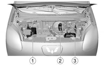
FRONT CABIN
- 12V battery
- Brake fluid reservoir
- Windshield washer fluid bottle
12V battery
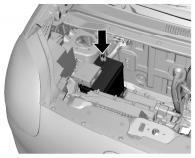
12V BATTERY
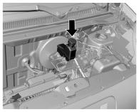
BRAKE FLUID RESERVOIR
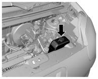
WINDSHIELD WASHER FLUID
BOTTLE
12V battery is located under the front compartment.
Brake fluid
The vehicle has a brake fluid reservoir. Brake fluid absorbs moisture, and excessive moisture in the fluid can reduce the efficiency of the hydraulic brake system. Replacing the fluid according to the instructions in this manual will prevent corrosion in the hydraulic system. Always use brake fluid recommended by MCrown Auto. Fill the reservoir to the appropriate level. The level should not be below the MIN (minimum) mark or above the MAX (maximum) mark. A low brake fluid level may be caused by a brake system leak or normal wear of the brake pads / linings. Consult a qualified service center to determine if the system requires repair. If so, refill the fluid after repairing the hydraulic brake system. When the brake fluid level drops below the lower limit, the brake system warning light illuminates. Refer to the “Instruments and Controls” section for information on brake system warning lights.
Add brake fluid
- Wipe away any dirt around the tank filler cap thoroughly.
- Unscrew the filler cap.
- Fill the tank with MCrown Auto-recommended brake fluid to the MAX mark. Be careful not to spill fluid onto painted surfaces. If spilled, immediately rinse the affected area with cold water.
- Reinstall the fluid tank filler cap.
Reducer oil
Check whether the reducer oil is leaking
This work requires specialized skills and equipment. To avoid personal injury or vehicle damage, we recommend that you have this work performed at an authorized repair center.
Windshield washer fluid
Before driving, make sure the reservoir is filled with an adequate volume of the specified washer fluid. In cold weather, do not overfill the windshield washer fluid reservoir. Washer fluid will expand due to ice formation at low temperatures. Overfilling the tank will not allow enough expansion space and may damage the tank.
Windshield wipers
Foreign matter on the windshield and wiper blades can reduce wiper effectiveness. If the wipers are not working properly, clean them with a dedicated or neutral detergent. Rinse thoroughly with water. Repeat as necessary. Do not use corrosive substances or substances that cannot be removed from glass (such as silicone) to clean the windshield. There is a layer of graphite on the surface of the rubber strip, which plays a role of lubrication and protection. Excessive wiping and improper polishing should be avoided. Do not start the wipers when the glass surface is dry; try to park the vehicle in a cool place to prevent high temperature exposure from accelerating the aging and deformation of the rubber strips. Before activating the wipers, be sure to clean off bird droppings, dust, leaves and other foreign objects on the glass surface, otherwise the service life of the wipers will be shortened.
Wiper service location *
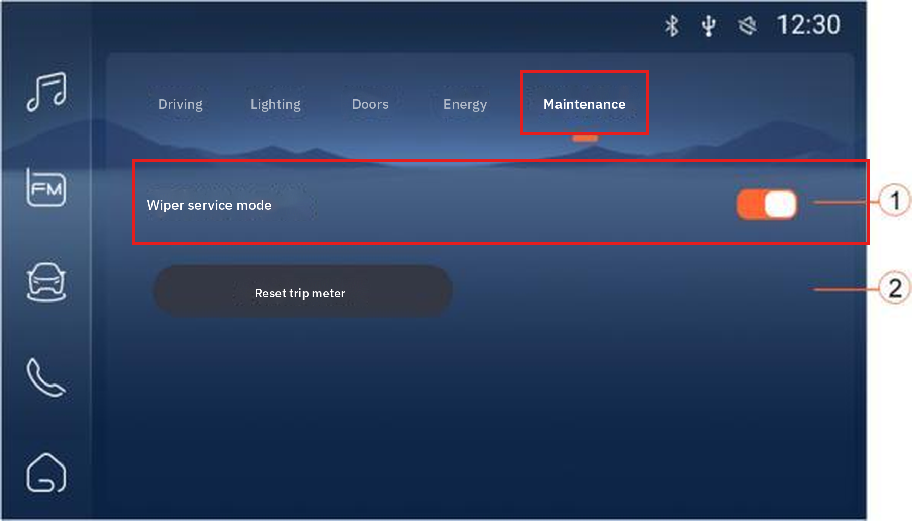
[VEHICLE MAINTENANCE] – WIPER REPAIR SWITCH
Depending on the configuration, some models can turn the wiper maintenance function on or off on the vehicle’s central control screen. Click the [Vehicle Control] icon in the left navigation bar, drop-down menu, or all applications to enter the [Vehicle Maintenance] settings interface, open the [Wiper Repair] [Effective] switch, the scraper arm automatically swings to the maintenance position. After replacing the wiper blade, lower the wiper arm, turn off the [wiper maintenance function] switch, and the wiper will return to its original position.
Replace wipers
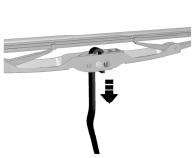
SEPARATE THE WIPER BLADE
As shown in the figure, first adjust the wiper blade to an angle perpendicular to the wiper arm, then press the wiper blade in the direction of the arrow to separate the wiper blade from the wiper arm. To install the scraper, follow the reverse steps.
Brake pedal
Check brake pedal travel
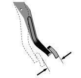
CHECK BRAKE PEDAL TRAVEL
Brake pedal travel: To avoid affecting pedal travel, do not lay thick carpet in the brake pedal area. The reasonable range of free travel of the brake pedal is ≤ 6.6 mm. If you find that the brake pedal does not return to its original position or the brake pedal travel becomes longer, please go to a special maintenance service center for inspection. This may indicate that there is a problem with the brake system.
Fuse
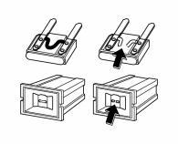
USE A FUSE EXTRACTOR
To replace the fuse:
- Open the fuse box cover.
- Identify the damaged fuse by the blown fuse.
- Use a fuse extractor to remove the blown fuse. The fuse extractor is located inside the fuse box cover.
- Determine the cause of the blown fuse and correct the problem.
- Install a new fuse with a specified rated current.
If necessary, ask an authorized repair service center to replace it for you.
Fuse box
The vehicle’s fuse box is located in the dashboard in front of the passenger seat.
Car fuse box layout
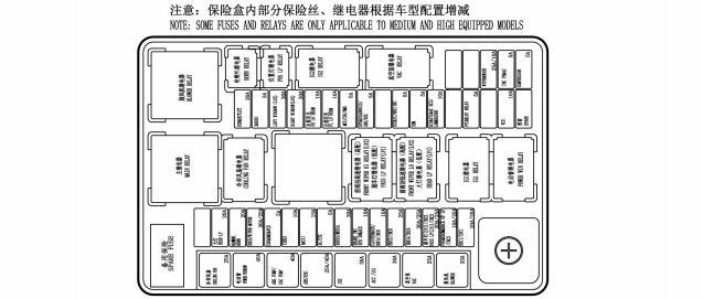
CAR FUSE BOX LAYOUT
The layout of components inside the fuse box may vary depending on the vehicle model or configuration. Please refer to the actual vehicle for details.
Light bulb replacement
Like foggy headlights
Since a lot of heat is generated when the headlights are on, it needs to be dissipated through the vents on the lamps. The lamp is not completely sealed, and moist air can enter the lamp through the vents. When the temperature inside the lamp is significantly higher than the ambient temperature or the ambient humidity is high, such as in cold or humid weather conditions, or when the vehicle is driving in the rain or after washing the car, the water vapor inside the lamp will condense on the surface of the lampshade to produce water mist. (Similar to the fogging phenomenon of car windows) This is a normal natural phenomenon and will not affect the lighting function or service life of the headlights. Park the vehicle in a dry, ventilated area, and the moisture will gradually dissipate until it disappears. Driving with the lights on or in sunlight will accelerate the dissipation of the mist, but some residue may remain around the corners of the headlights. 2-3 days for the water mist to completely dissipate. If there are large amounts of water droplets or water accumulation in the lamp, please contact a service center for inspection.
Bulb specifications
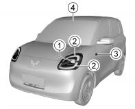
FRONT
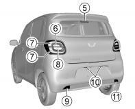
REAR
| SERIAL NUMBER | LIGHT BULB | POWER X QUANTITY | REMARK |
| 1 | Low beam / high beam | Type I: 55W×2 / Type II: LED | Type I: H7 |
| 2 | Front position lights / front turn signal lights / hazard warning lights | led | |
| 3 | Side turn signal lights | 5W×2 | W5W |
| 4 | Front reading lights | led | |
| 5 | High-mounted brake light | led | |
| 6 | rear brake light | led | |
| 7 | Rear position lights | led | |
| 8 | Rear turn signal lights / hazard warning lights | led | |
| 9 | rear fog lamp | 21W×1 | P21W |
| 10 | Rear license plate light | led | |
| 11 | Reversing lights | 21W×1 | P21W |
Wheels and tires
Original equipment tires provide the best match between ride comfort, tread life and performance. This vehicle does not come with a spare tire, jack, or socket wrench If you need to replace the tire, please contact a service center for wheel and tire replacement.
Maintainance
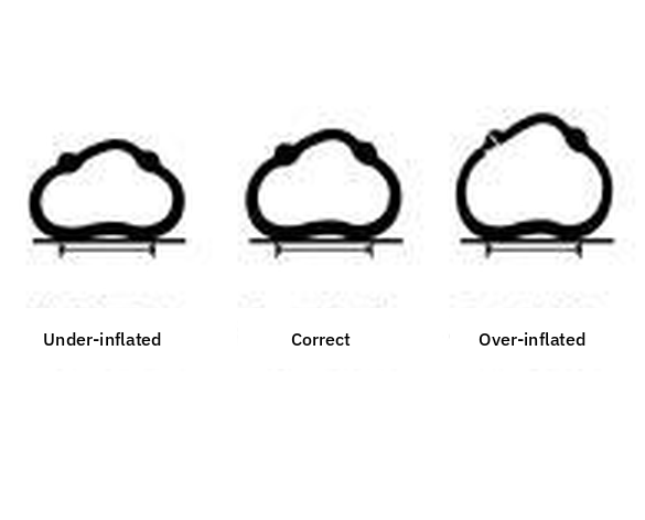
UNDER-INFLATED · CORRECT · OVER-INFLATED
Tire pressure should comply with the regulations in this manual to ensure optimal matching of driving comfort, safety and driving performance. See the “Technical Data” chapter for correct tyre pressures. Check the tire pressure with an accurate tire pressure gauge when the car is cold. After checking the tire pressure, tighten the valve core cap.
Maintaining tires and wheels
Running over sharp objects can damage tires and wheels. If you have to run over such objects, slow down and drive slowly. Avoid hitting the curb when parking. Check your tires regularly: External damage. Foreign object. Puncture. Cut. Crack. Side wall protrusion. The wheels should also be inspected for damage. Tire defects, including those listed above, can cause loss of vehicle control and result in personal injury. If your tires or wheels are damaged or show abnormal wear, please consult a designated repair center. Your vehicle is equipped with radial tires. MCrown Auto recommends replacing them with radial tires of the same size, pattern, tread wear, temperature, and speed rating.
Built-in tread wear indicator
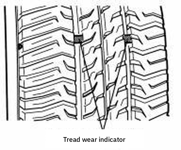
TREAD WEAR INDICATOR
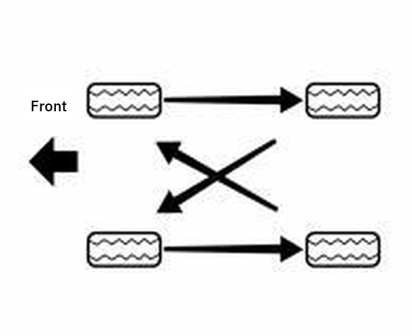
TIRE ROTATION
Check the tire tread depth regularly according to the tread wear indicators. The markings on the sidewall indicate the location of the tread wear indicators. Tires must be replaced when the tread wear indicators appear. These appear between the tread grooves when the tread depth is 1.6 mm or less.
Tire rotation
Front and rear tires perform different functions and therefore wear differently. Front tires typically wear faster than rear tires. To extend tire life and avoid uneven tread wear:
- Rotate tires according to the maintenance procedures in this manual.
- Maintain proper tire pressure.
- Check the tightness of nuts / bolts.
Winter tires
Using winter tires can improve driving safety on icy and snowy roads. Choose winter tires with radial construction and use them on all four wheels. Always use the specified tire pressure and never exceed the maximum speed specified by the tire manufacturer. In addition to winter tires, all-season tires are also an option.
Tire chains
Snow chains are only for emergency use or in areas where they are clearly defined by law. Snow chains should be installed on the drive wheels. Be extra cautious when driving a vehicle with snow chains installed. Compared to tires without snow chains, the maneuverability of the vehicle is better when snow chains are installed on the tires. Chains that are poorly secured may damage the vehicle’s tires, suspension, or body. Therefore, thin chains should be used to ensure adequate clearance between the tires and other components within the wheel arch. When using tire chains, carefully read the manufacturer’s installation and other instructions.
Jump starting (dead battery)
If you cannot unlock and enter the vehicle with the remote control, or the instrument cluster does not display anything, it may be 12V battery is low. You can use another car’s 12V battery to power your vehicle. If the vehicle has no power, you should have sufficient electrical knowledge to ensure that you can complete this work safely. Otherwise, please call the service center to handle it for you.
Preparation before jump starting
- Apply the parking brake.
- Turn off all electrical accessories.
Connecting the jumper cables — When jump starting your vehicle, connect the jumper cables in the following order:
- Clamp one end of the first jumper cable to the positive terminal of the charged battery. (There is a “+” mark).
- Clamp one end of the jumper cable to the positive terminal of the depleted battery. (The terminal is marked with a “+”).
- Clamp one end of the second jumper cable to the negative terminal of the charged battery. (The battery casing or terminal is marked with a “-”).
- Connect the other end of this cable to the ground connection on the vehicle.
- After connecting the jumpers, follow the starting procedure to put the vehicle into READY mode and start it.
- Carefully remove the jumper cables in reverse order, removing the negative cable first, then the positive cable.
- Keep the vehicle in READY mode or charge it for at least 2 hours for better maintenance of the 12V battery.
It is recommended that you contact a service center as soon as possible for a dedicated 12V battery charge. Note: Push-starting an electric vehicle is not possible.
Towing vehicle
If you need to tow your vehicle, please contact an authorized repair service center or a professional towing service company.
Towing your vehicle with a wheel lift
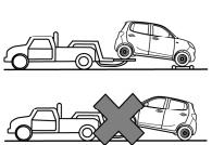
TOWING WITH A WHEEL LIFT
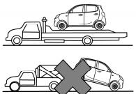
FLATBED TRAILER
- Turn on the hazard warning flashers.
- Turn the power switch (if equipped) to the ACC (Electrical Accessories) position.
- Release the parking brake or turn off the automatic clamping function of the electronic parking brake (if equipped).
- The rear wheels must be off the ground when towing.
Shipping your vehicle on a flatbed trailer
When transporting the vehicle on a flatbed trailer, turn off the power switch (if equipped). Check that the vehicle is securely fastened to the trailer. Your vehicle may only be towed by other vehicles and may not be used to tow other vehicles.
Emergency Tow Truck
If there is no towing vehicle on site in an emergency, you can temporarily tow the vehicle by attaching a rope to the front tow hook under the vehicle. When towing a vehicle with the front tow hook, only use the tow rope, not a hard tow bar.
Front tow hook
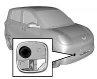
FRONT TOW HOOK MOUNTING HOLE
There is a hole cover on the front bumper of the vehicle. Remove the cover to reveal the mounting hole for the tow hook. Place the tow hook in the tool bag, remove it, and install it in the mounting hole. Turn the tow hook clockwise to tighten it firmly. If necessary, insert a socket wrench into the tow hook hole to assist in tightening. Ensure the tow hook is securely installed before towing the vehicle. The driver must always be in the vehicle to control steering and braking. After towing, remove the tow hook, close the hole cover, and return the tow hook to its original position.
Get out of a stuck car situation
If you are stuck in snow, mud or other unstable surfaces, please refer to the following steps to get out of the situation.
- Turn the steering wheel fully to the left, then fully to the right. This will create a gap around the front wheels.
- Shift back and forth between reverse gear and forward gear.
- Reduce wheel spin as much as possible.
- After engaging the gear, lightly press the accelerator pedal.
If you cannot get out of trouble after a few attempts, you will need towing.
Cleaning agents
When cleaning the interior and exterior of a car, unless specifically instructed to remove stains in the fabric cleaning recommendations, the following cleaning agents are prohibited: Laundry soap, Bleach, Restoring agent, Acetone, Paint thinner, Ceramic enamel restorer, Nail polish remover.
To avoid permanent discoloration of light-colored interiors, do not allow easily fading fabrics to come into contact with the seat linings unless both materials are completely dry. The following are listed fabrics containing easily fading materials: Casual wear, Dyed twill, Leather, Kidskin, Newspapers and decorative paper.
Interior maintenance and cleaning
Always use appropriate cleaning methods and materials to clean the inside and outside of your vehicle. Frequently use a vacuum cleaner or a soft-bristled brush to remove dust and loose dirt that has accumulated on the fabrics in your car. Wipe vinyl and leather trim regularly with a clean, damp cloth. Use a suitable cleaner to clean dust, spots or stains from the trim.
Seat belt maintenance
Keep seat belts clean and dry. Protect seat belts from contamination with polishes, oils, and chemicals, especially battery fluid, bleach, or dyes. These contaminants can weaken the seat belt material. Inspect all seat belt parts regularly. Replace any damaged seat belts or components immediately. Any related part that has been stretched in an accident must be replaced, even if the damage is not obvious or visible. Replacement seat belts must be new. MCrown Auto recommends replacing the entire seat belt assembly after a collision. If the seat belt is inspected by a designated repair center and found to be undamaged and in good working order, it is not necessary to replace the seat belt.
Glass surface
Keeping your car windows clean helps reduce glare and improve your vision.
Clean the outside of the windshield
Wax or other materials on the windshield and wiper blades can cause the wiper blades to vibrate when working. In addition, such foreign matter is not conducive to keeping the windshield clean. Clean the windshield exterior regularly with a non-abrasive cleaner. Water will not bead up on a clean windshield.
Exterior vehicle maintenance and cleaning
Washing the vehicle
Be sure to turn off the power before washing the car, inform the car washer that the car is a pure electric vehicle, and do not use a water gun to rinse the front cabin and front grille, as well as the power battery under the car. The best way to maintain your vehicle’s paint is to wash it regularly and keep it clean. Park the vehicle in a location where it will not be exposed to direct sunlight. Wash the car with the specified neutral soap and cold or warm water. Be sure to rinse off all soap and detergent residue.
MCrown Auto vehicles are designed to operate under normal environmental conditions and natural factors.
Polishing and waxing
Regular polishing can remove residue from the vehicle surface. After polishing, use high-quality car wax to protect it.
Protective car exterior bright metal parts
Clean shiny metal trim regularly. Rinsing with water is usually sufficient. When waxing your car, don’t forget to wax the shiny metal trim as well.
Cleaning aluminum wheels and wheel caps
To keep the original appearance of the wheels and wheel covers (if any), do not allow them to collect dust or brake dust. Clean the wheels / wheel covers regularly without using abrasive cleaners or brushes that could damage the finish.
Anti-corrosion
MCrown Auto vehicles are designed to be corrosion-resistant. Special materials and protective paints are used on most vehicle parts to help maintain their appearance, strength, and reliability. Although some parts in the front cabin or underbody may develop surface rust, it will not affect the reliability or functionality of these components.
Sheet metal damage
If the car body needs repair or replacement, make sure the repair shop uses suitable anti-corrosion materials to restore the corrosion protection.
Foreign matter deposition
The following substances can damage painted surfaces: Calcium chloride and other salts, Ice-melting agents, Road coatings and asphalt, Tree sap, Bird droppings, Industrial dust. Clean the harmful substances on the car promptly. If soapy water cannot remove the residue, use a special cleaning agent.
Damage to topcoat
Repair stone chip scratches, cracks, or deep scratches in the paint as soon as possible. Bare metal corrodes easily. Minor cracks and scratches can be repaired with a quick-drying product. A body and paint shop can perform larger repairs.
Underbody maintenance
Corrosive substances used in de-icing, de-snowing, and dust control can accumulate on the underbody of your vehicle. Failure to remove these substances can accelerate corrosion and rust. Loosen any dirt that has accumulated in enclosed areas before rinsing. If necessary, please ask a specially authorized maintenance service center to provide you with this service.
Technical Data
Vehicle Identification
Vehicle Identification Number (VIN)
markings commonly found on your vehicle are located below.
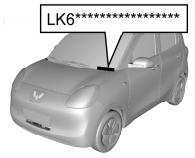
VEHICLE IDENTIFICATION NUMBER ON
THE DASHBOARD
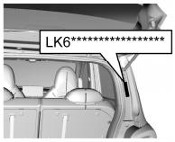
TAILGATE VEHICLE IDENTIFICATION
NUMBER
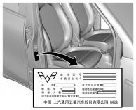
VEHICLE IDENTIFICATION PLATE
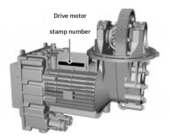
DRIVE MOTOR STEEL STAMP NUMBER
Vehicle identification number on the dashboard — This is the legal identification mark for your vehicle. The VIN is located on the front corner of the dashboard, on the driver’s side. It is visible through the windshield from outside the vehicle.
Tailgate Vehicle Identification Number — Located on the tailgate frame.
Vehicle identification plate — The sign is a paper sign located on the door frame of the passenger side door.
Drive motor steel stamp number — The stamped number is located on the motor housing.
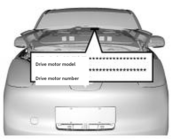
LOCATED ON THE FRONT HOOD
Read the vehicle VIN code using the aftermarket diagnostic system
- Connect the data cable of the diagnostic system to the OBD port on the car. The OBD port on the car is usually located under the dashboard on the driver’s side.
- Turn on the vehicle power and put the vehicle in READY state, and turn on the diagnostic system.
- Select the “Basic Diagnosis” option, read the corresponding vehicle model, click to enter the “Vehicle Controller Module” interface, and then find the Vehicle Identification Number (VIN) in the content list.
Microwave windows and electronic signs
The microwave window is the area where electronic identification signals are transmitted. can be used as a microwave window without any shielding. It is recommended to affix the electronic label to the inside of the front windshield, above the right side of the rearview mirror. Electronic sign signals cannot be blocked or shielded, so do not apply glass film before applying electronic signs. If your region has different requirements for the installation and implementation time of electronic signs, please refer to local regulations.
Vehicle data
Main types and parameters of chargers, charging plugs and sockets
| PROJECT | UNIT | LZW 7001 EVC 1 / LZW 7001 EVC 2 | LZW 7001 EVD 1 / LZW 7001 BEVA 1 |
| On-board charger model | — | CDU-312-033-10 | CDU-312-033-10 |
| On-board charger rated input voltage / current / frequency | V/A/Hz | 90-264/16/50 | 90-264/16/50 |
| On-board charger output voltage / current / power | V/A/kW | 200-470/13/3.3 | 200-470/13/3.3 |
| Charging plug model | — | AC plug: C01-1C11122-10A; HVCAG 2M10A | AC plug: C01-1C11122-10A; HVCAG 2M10A |
| Charging socket model | — | AC socket: CL-C5 GIA 02; WOER-GB-I-AC 16/DC 80-07; GNCZ-AC 16-YT 02; Straight Flow socket: CL-C5 GID 10T; WOER-GB-I-AC 16/DC 80-07; GNCZ-DC 80-YT 01 | AC socket: CL-C5 GIA 02; WOER-GB-I-AC 16/DC 80-07; GNCZ-AC 16-YT 02; Straight Flow socket: CL-C5 GID 10T; WOER-GB-I-AC 16/DC 80-07; GNCZ-DC 80-YT 01 |
| Charging method | — | Constant current and constant voltage charging | Constant current and constant voltage charging |
Main parameters and performance indicators of drive motor
| PROJECT | UNIT | LZW 7001 EVC 1 / LZW 7001 EVC 2 | LZW 7001 EVD 1 / LZW 7001 BEVA 1 |
| model | — | TZ 155 XZ 230 | TZ 155 XZ 230 |
| type | — | permanent magnet synchronous motor | |
| Peak power | kW | 30 | |
| Peak torque | N·m | 85 | |
| Peak speed | r/min | 12000 | |
Main performance parameters of power battery system
| PROJECT | UNIT | LZW 7001 EVC 1 | LZW 7001 EVD 1 | LZW 7001 EVC 2 | LZW 7001 BEVA 1 |
| type | — | lithium iron phosphate battery | |||
| type | — | Energy | |||
| Single battery model | — | IFP 28148115-52 Ah | A: IFP 28148115-52 Ah, B: CBKP 0, C: LFR 65120-50 Ah | LFR 60120-42.5 Ah | A: CBKP 0, B: LFR 65120-50 Ah |
| voltage of single battery | V | 3.15 | A: 3.15, B: 3.12, C: 3.16 | 3.15 | A: 3.12, B: 3.16 |
| Total mass | kg | 134 | A: 134, B: 134, C: 132 | 133 | A: 134, B: 132 |
| Total energy | kWh | 16.2 | 16.2 | 16.3 | 16.2 |
| Total nominal voltage | V | 312 | A: 312, B: 318, C: 325 | 384 | A: 318, B: 325 |
| Total nominal capacity | Ah | 52 | A: 52, B: 51.2, C: 50 | 42.5 | A: 51.2, B: 50 |
| Rated output current | A | 52 | A: 52, B: 51.2, C: 50 | 42.5 | A: 51.2, B: 50 |
Main quality parameters of the vehicle
| PROJECT | UNIT | LZW 7001 EVC 1 / LZW 7001 EVC 2 | LZW 7001 EVD 1 / LZW 7001 BEVA 1 |
| Number of passengers | people | 2 | 2 |
| Curb weight | kg | 760 | 780 |
| Curb front axle load | kg | 387 | 388 |
| Rear axle load after adjustment | kg | 373 | 392 |
| Maximum allowable total mass | kg | 1060 | 1100 |
| Fully loaded front axle load | kg | 475 | 475 |
| Fully loaded rear axle load | kg | 585 | 625 |
Main dimensional parameters of the vehicle
| ITEM | UNIT | LZW 7001 EVC 1 / LZW 7001 EVC 2 | LZW 7001 EVD 1 / LZW 7001 BEVA 1 |
| Total Length | mm | 3256 | 3256 |
| Overall width | mm | 1510 | 1510 |
| Total height (unloaded) | mm | 1578 | 1578 |
| wheelbase | mm | 2190 | 2190 |
| front overhang | mm | 592 | 592 |
| rear overhang | mm | 474 | 474 |
| Front track | mm | 1282 | 1282 |
| rear track | mm | 1290 | 1290 |
| Approach angle (empty / full) | ° | 22 | 22 |
| Departure angle (empty / loaded) | ° | 38 | 38 |
| Minimum ground clearance (fully loaded) | mm | 120 | 120 |
| Minimum turning diameter | m | 9.2 | 9.2 |
Names and locations of components not included in the vehicle’s overall dimensions according to GB 1589
| NAME | LOCATION |
| Wipers and washers | rear of the vehicle |
| External markings, including product trademarks, company name markings, and other markings reflecting vehicle characteristics | Front, rear, and side of the car |
| Lights and light signaling devices | Front, rear, and side of the car |
| Rear sign plate with LOGO | rear of the vehicle |
| Detachable vehicle hitch or towing device | Front of the car |
| Indirect vision device | Front, rear, and side of the car |
| Anti-collision rubber blocks and similar devices | Side of the car |
| Flexible protrusions of splash protection systems | Side of the car |
| Handle, switch | Side of the car |
| The deformed portion of the tire wall just above the tire’s contact point | Tire side |
| NAME | LOCATION |
| The soft part of the antenna | roof |
Power performance parameters
| PROJECT | UNIT | LZW 7001 EVC 1 / LZW 7001 EVC 2 | LZW 7001 EVD 1 / LZW 7001 BEVA 1 | TEST METHOD |
| Start shifting and accelerating to Time required to reach 50 km/h | s | 7.0 | 7.0 | GB/T 18385 — 2005 |
| 50 km/h acceleration Time required to reach 80 km/h | s | 9.0 | 9.0 | |
| Maximum speed | km/h | 90 | 90 | |
| 30-minute maximum speed | km/h | 90 | 90 | |
| Maximum climbing grade | % | 20 | 20 | |
Economic parameters
| PROJECT | UNIT | LZW 7001 EVC 1 / LZW 7001 EVC 2 | LZW 7001 EVD 1 / LZW 7001 BEVA 1 | TEST METHODS |
| Cruising range (CLTC) | km | 205 | 205 | GB/T 18386.1 — 2021 |
| Power consumption rate (working condition Law) | Wh/km | 89 | 89 | |
Main liquid parameters
| NAME | BRAND | CAPACITY |
| Reducer oil | ERO 75W | 1.0±0.05 L |
| brake fluid | DOT4 | 0.55 L |
| Air conditioning refrigerant | HFC-134a | 300 g ± 20 g |
Tire inflation pressure (cold)
| TIRE MODEL | ITEM | TIRE INFLATION PRESSURE (FULLY LOADED) (UNIT: KPA) |
| 155/70R13 | front wheel | 250 |
| rear wheel | 250 |
Wheel alignment parameters (no load)
| PROJECT | RANGE (UNIT: DEGREES) | |
| front wheel | camber angle | 1°0′, ±45′ |
| Caster angle | 3°41′, ±45′ | |
| toe angle | 0°12′, ±5′ | |
| Kingpin inclination angle | 9°46′, ±1° | |
| rear wheel | camber angle | / |
| toe angle | 0±15′ |
Other parameters
| ITEM | PARAMETER |
| Wheel dynamic balancing requirements | Dynamic unbalance <22 g |
| Reasonable range of brake pedal free travel | ≤ 6.6 mm |
| Minimum thickness of front brake disc scrap | 6 mm (1 mm per side) |
| New brake shoe friction lining thickness (standard) | 4.9 mm |
| Minimum thickness of friction material (brake pad / brake shoe) | About 1.6 mm |
| Rear brake drum inner diameter limit | 205 mm |
Maintenance procedures
Important Information
- We recommend that you visit our authorized service centers for vehicle maintenance and repairs. They are the only ones who understand your vehicle best and will provide you with genuine parts and professional technical service. This quality assurance is only guaranteed at our authorized service centers. Non-family vehicles (such as company vehicles) are covered by the warranty period, while family vehicles are covered by both the warranty period and the “Three Guarantees” period.
- The company is not responsible for any problems caused by the use of non-original parts (including but not limited to other violations of laws and regulations caused by the use of non-original parts).
- If regular maintenance is not performed as required during the warranty period, the warranty service will not be provided for any maintenance-related issues or any faults caused by the maintenance. The first maintenance must be performed after 6 months or 5,000 kilometers (whichever comes first). This maintenance must be performed at the service center with the purchase invoice and this manual.
- This manual must be presented to the service center during maintenance or repair. Please keep this manual and the maintenance and repair information recorded in it properly. They are important bases for you to enjoy quality assurance services and for the service center to analyze the cause of failure. The maintenance record sheet must be stamped by the service center. The service center has no right to keep your manual, and the service center cannot refuse to provide quality assurance service for your car for any reason if the vehicle meets the quality assurance service conditions.
- The user submits a written request for return or exchange of the vehicle. After final appraisal and confirmation by MCrown Auto Automobile Co., Ltd., the dealership can handle the return or exchange procedures for the car and charge a usage compensation fee based on the purchase price (based on the invoice of the car seller) and mileage. Calculation formula: vehicle price (yuan) × mileage (km) / 1000 (km) × 0.5%.
- After the driver leaves the vehicle, please do not store valuables in the vehicle. Otherwise, if any valuables are lost, the company will not bear any responsibility.
- If you need assistance, please contact any of the service centers closest to you or call MCrown Auto Automobile Co., Ltd.
- If the official product recall information is released, our company or our authorized service center will notify you by phone, text message, letter, etc. After receiving the notification, please cooperate to deliver the vehicle to the designated location, or make relevant vehicle preparations as required. Product recalls are an effective guarantee for the safety of your vehicle, so please cooperate actively.
- The time and mileage in this manual are based on the first arrival date. If it is not necessary, no special instructions will be given. Any matters not covered in this manual or that are inconsistent with relevant national laws and regulations shall be subject to relevant national laws and regulations. Regulations shall prevail.
Original accessories introduction
1. Introduction to original accessories
Genuine Parts: Parts manufactured by authorized YT AUTO suppliers and certified by YT AUTO’s quality standardization system. Counterfeit Parts: Parts that realistically imitate the external features of other similar products, or unauthorized copies and sales of products protected by intellectual property rights, used to impersonate genuine parts. Inferior Parts: Parts whose quality and performance do not meet the requirements stipulated in my country’s national, industry, and local standards, or even parts manufactured without standards.
2. Advantages of original accessories
Quality Assurance, Worry-Free Service: Genuine parts are manufactured by qualified suppliers according to standardized production quality standards, ensuring quality and long service life. They also come with nationwide warranty service, providing peace of mind during maintenance and use. Safety, Reliability, and Superior Performance: Genuine parts are perfectly matched to your vehicle, guaranteeing excellent performance and safe driving. Using non-genuine parts can easily lead to secondary malfunctions in the vehicle or its components, increasing repair costs and driving safety risks.
3. Identification of anti-counterfeiting marks on original accessories
All MCrown Auto certified original parts will have MCrown Auto printed on the outer packaging. The LOGO logo is as shown below. Users should strengthen their identification when purchasing and using original accessories to avoid counterfeiting.
4. Original parts service supervision hotline
MCrown Auto and its entire service system are committed to using original accessories to provide services and not using counterfeit or inferior accessories. MCrown Auto and its service providers are committed to being transparent about the source and quality assurance of genuine parts and will never use non-genuine parts without authorization. When using non-genuine parts, the reasons must be explained to the user, and the procurement source and quality assurance materials of the non-genuine parts must be disclosed. The parts can only be used after consultation with the user and obtaining the user’s consent. MCrown Auto and its entire system of service providers promise to make the prices of original accessories open and transparent. The sales price must be clearly stated to the user and confirmed by the user’s signature. A user who finds that the 4S store violates the service commitment of original accessories during repair or maintenance, can directly call the local MCrown Auto dealer. The above content includes the latest information as of the time of publication of this manual. If there is any update, please refer to the actual product.
Warranty
Provisions for quality assurance services
- During the quality assurance period, due to product design, manufacturing Vehicle defects caused by manufacturing, assembly, and raw material defects will be identified by MCrown Auto Automobile Co., Ltd. or its service center. To protect the environment and promote sustainable development, the company will primarily repair defective parts free of charge. Part replacement will only be adopted when defective parts cannot be repaired or have no repair value. Parts used for repair or replacement must be provided by the manufacturer or approved and inspected to be qualified.
- During the warranty period, if your vehicle requires necessary repairs due to defects within the scope of warranty service, please allow the service center reasonable and sufficient time to carry out the necessary repairs. The service center will return your vehicle to you as quickly as possible, and the parts replaced under warranty will become the property of our company.
- Except for the mandatory provisions of Chinese laws, the quality assurance service provided by this manual and the vehicle manual is the sole responsibility of our company to the user.
- The transportation time of special parts and the time occupied in the rescue trip are not included in the repair time. The definition of special parts can be found in the appendix of the three guarantees certificate.
- Non-family cars (such as company cars, etc.) enjoy the service within the warranty period, and family cars enjoy the warranty period. Services within the warranty period and the three-guarantee period.
User Rights and Obligations
For new vehicle parts and accessories at your own expense, users are entitled to quality assurance services provided they fulfill their basic obligations and comply with other relevant provisions of this manual. The following are the basic obligations that users must fulfill in order to enjoy the quality assurance services:
- During the quality assurance period, please go to the service center for regular maintenance according to the provisions of this manual, and use and operate the product correctly according to the provisions of this manual.
- Use genuine accessories provided by our company, and all maintenance, repairs, replacements, etc. are carried out in the service center and valid certificates can be provided.
- To ensure the safety of both the user and the vehicle, users should maintain the vehicle in its original condition as much as possible and contact MCrown Auto Co., Ltd. or a service center as soon as possible. Disassembly or repair without the permission of MCrown Auto Co., Ltd. or a service center is prohibited.
- According to national regulations, the user’s waste power batteries must be recycled by a qualified recycling company. The service center provides free recycling services for waste power batteries. The company does not assume any responsibility for any violation of national regulations caused by the user’s private disposal of waste power batteries.
Scope of Quality Assurance Services
- Defects within the scope of quality assurance service: refers to vehicle defects caused by factors such as product design, manufacturing, assembly and raw material defects, which are identified by MCrown Auto Automobile Co., Ltd. or the service center during the quality assurance period.
- During the warranty period, the user will not be charged for material costs and labor costs incurred for vehicle repairs due to defects within the warranty service scope.
- Auxiliary material fees that must be incurred due to quality assurance services will not be charged to users.
Not within the scope of quality assurance service
- Forging or illegally obtaining relevant vehicle purchase certificates, vehicle manuals, etc.
- Failure to produce the purchase invoice when required to prove vehicle purchase information;
- Expired the warranty period or failed to produce this manual. If you fail to produce the relevant documents for applying for a replacement of this manual, or fail to produce this manual, the purchase invoice and settlement statement issued by the service center at the same time for self-paid accessories;
- Failure to fully perform basic user obligations;
- Failures caused by changes to the original vehicle structure such as unauthorized installation, modification or addition of equipment;
- Cheating behavior during the quality assurance period, including but not limited to intentionally changing the odometer;
- Refuse to accept the quality assurance service of MCrown Auto Automobile Co., Ltd. or service center;
- Secondary failures caused by continuing to drive a car when it breaks down.
- Product failure or parts loss caused by improper use, storage, or maintenance by the user, including but not limited to failure of electrical equipment or other parts due to water exposure, or failure caused by theft, overloading, abnormal operation, racing, exposure to sunlight, or long-term parking;
- Damage caused by traffic accidents, natural disasters or other force majeure, including but not limited to car accidents, floods, sandstorms, earthquakes, hail, mudslides, military operations, etc.;
- In addition to the initial maintenance, maintenance materials that require regular replacement;
- Damage caused by human or external factors, Defects such as rust, discoloration, scars, etc., including but not limited to scratches by foreign objects, animal excrement stains, Pollution, environmental pollution, etc.
- Under normal circumstances, it will not affect the quality of the car, Sensory phenomena that affect the function of the device, including but not limited to slight noises or vibrations;
- Financial losses or additional expenses caused by the vehicle not being able to be used normally, such as loss of time, personal property and income.
- The capacity of all lithium batteries will gradually decrease after a period of use. The normal loss of capacity of the lithium battery of this electric vehicle is not within the scope of the three guarantees.
Quality assurance period
The quality assurance period is divided into the original car parts quality assurance period and the self-paid accessories quality assurance period according to the parts. The original car parts quality assurance period is divided into the warranty period and the three-guarantee validity period according to the nature, and the self-paid accessories quality assurance period is only the warranty period. The quality assurance period does not change with the change of vehicle ownership, but if the sales unit and the user have signed other agreements, the signed agreement shall prevail, and the relevant policies and terms of this manual will not apply. For example, if the sales unit and the user have signed a second-hand car sales agreement, an inventory price reduction car agreement, an agreement to notify a defective vehicle, etc., the specific definition of the quality assurance period is as follows:
- Original car parts quality guarantee period: refers to the quality guarantee enjoyed by the original car parts when purchasing a new car. The warranty period is calculated from the date of purchase (based on the seller’s invoice) and the mileage at that time. The purchase date will be indicated on the “Three Guarantees Certificate” in this manual and signed by the user. The original parts warranty period is divided into a repair period and a “Three Guarantees” validity period. Detailed information is provided in the appendix to the “Three Guarantees Certificate.” When the user requests the original vehicle parts quality assurance service from the service center, this manual must be presented. If the odometer is invalid or damaged and not repaired in time, making it impossible to confirm the mileage, the mileage shall be calculated as 300 kilometers per day from the date of purchase; if there is a quality assurance service record, the mileage shall be calculated as 300 kilometers per day from the date of repair, and the mileage shall be accumulated together with the mileage recorded on the date of repair; if the odometer has been replaced, it shall be calculated cumulatively with the mileage of the previous odometer.
- Warranty period: refers to the time and mileage range during which warranty repairs are provided free of charge under the conditions of compliance with the relevant policies and terms of this manual and relevant national laws and regulations.
- Three guarantees validity period: refers to the time and mileage range for repair, replacement and return under the conditions of complying with the relevant policies and terms of this manual and relevant national laws and regulations. Currently, there is no three guarantees validity period for self-paid accessories.
- Quality guarantee period of self-paid accessories: refers to the original accessories purchased by users at the service center at their own expense. Items, from the date of purchase (based on the purchase invoice The calculation starts with the mileage at that time The purchase date and mileage at that time will be noted on the purchase invoice by the service center and signed by the user for confirmation. When the user requests the self-paid parts quality assurance service from the service center, he/she shall present this manual, the purchase invoice and settlement statement issued by the service center.
If the mileage cannot be confirmed due to repair, the mileage will be calculated as 300 kilometers per day from the date of purchase. Calculate the accumulated mileage; if the odometer has been replaced, it should be calculated together with the mileage of the previous odometer. The quality assurance period of self-paid accessories does not include the three-guarantee validity period. For specific information, please see the table below:
Quality guarantee period for accessories at your own expense
| NO. | COMPONENT | THREE GUARANTEES VALIDITY PERIOD | WARRANTY PERIOD |
| 1 | Batteries, plastic parts, lamps, sun visors | none | 6 months or 10,000 kilometers |
| 2 | No parts mentioned for the whole vehicle | none | 12 months or 20,000 km |
Maintenance part
Maintenance purpose
Proper vehicle maintenance not only keeps your car in good working condition, but also helps protect the environment. To protect the environment and keep your car in good condition, please properly maintain your car.
Maintenance system — All matters stipulated in this system apply to vehicles within the quality assurance period, and are only suggestions or references for vehicles outside the quality assurance period.
- Your vehicle must receive its first maintenance within 6 months or 5000 km (whichever comes first). All maintenance, including the first maintenance and subsequent scheduled maintenance, is the sole responsibility of the user.
- Every maintenance by the user should be carried out at the service center, and the service center shall fill in the “Maintenance Record Sheet”, signed by the user after confirmation.
- For quality problems found during maintenance work The problem is handled in accordance with the provisions of the quality assurance service.
- The maintenance specification table specifies the time and mileage for each maintenance. During the warranty period, maintenance must be performed at the service center within the time limit specified in the maintenance specification table. After the maximum warranty period, it is recommended that you also perform appropriate maintenance at the service center according to the time and mileage intervals in the maintenance specification table (or earlier if appropriate).
Maintenance specifications
- 23 items of standardized maintenance — 23 standardized maintenance items are our company’s unique maintenance standards. Each maintenance will conduct a comprehensive inspection and maintenance of the vehicle exterior, front cabin, cab, and chassis. Each maintenance interval is 12 months or 10,000 kilometers, so that your vehicle is in good condition.
- Maintenance Project — According to your vehicle usage environment and vehicle condition, we will carry out corresponding maintenance on the vehicle as needed, such as brake and air conditioning system maintenance, glass cleaning, etc.
| 23 STANDARDIZED MAINTENANCE ITEMS | ITEM |
| Body appearance | 1. Vehicle appearance and accessories |
| front cabin | 2. DC / DC voltage |
| 3. 12V battery | |
| 4. High and low voltage wiring harness | |
| 5. OBD Diagnosis | |
| 6. Inspection of oil and its pipelines | |
| cab | 7. Power battery system |
| 8. User Connection Unit (TBOX / UCU) | |
| 9. Pedal inspection | |
| 10. Parking Check | |
| 11. Seats and seat belts | |
| 12. Full vehicle lighting | |
| 13. Wiper spray | |
| 14. Instrument cluster | |
| 15. Air conditioning system | |
| 16. Air conditioning filter | |
| chassis | 17. Drive motor |
| 18. Reducer | |
| 19. Power Battery | |
| 20. Steering system | |
| 21. Tightening of key chassis bolts | |
| 22. Braking | |
| 23. All tires |
For the vehicle’s 23 standardized maintenance items, if any abnormalities are found in the vehicle’s related parts, they need to be repaired in a timely manner and parts replaced if necessary.
Key maintenance items throughout the vehicle life cycle
- First maintenance: 6 months or 5,000 kilometers after the new car is sold, whichever comes first; replace the reducer gear oil during the first maintenance.
- Regular maintenance requirements: After the first maintenance, the interval between each subsequent maintenance is 12 months or 10,000 kilometers, whichever comes first.
- Routine Maintenance Specifications: When the vehicle is used on a flat, dusty road, perform maintenance according to the Routine Maintenance Specifications or in advance as appropriate. The time and mileage, whichever comes first, will be used.
| INTERVAL | STANDARD MAINTENANCE ITEMS | DEEP MAINTENANCE ITEMS |
| 6 months or 5,000 km | • 23-item standard maintenance • Replace reducer oil • Battery check | • Brake system care • Four-wheel alignment • Interior deep cleaning • Air-conditioning deep care • Power battery balancing care |
| 1 year 6 months or 15,000 km | • 23-item standard maintenance • Replace air-conditioning filter element • Battery check | • Brake system care • Four-wheel alignment • Interior deep cleaning • Air-conditioning deep care • Power battery balancing care |
| 2 years 6 months or 25,000 km | • 23-item standard maintenance • Replace brake fluid • Replace reducer oil • Battery check | • Brake system care • Four-wheel alignment • Interior deep cleaning • Air-conditioning deep care • Power battery balancing care |
| 3 years 6 months or 35,000 km | • 23-item standard maintenance • Replace brake pads • Replace air-conditioning filter element • Battery check | • Brake system care • Four-wheel alignment • Interior deep cleaning • Air-conditioning deep care • Power battery balancing care |
| 4 years 6 months or 45,000 km | • 23-item standard maintenance • Replace reducer oil • Battery check | • Brake system care • Four-wheel alignment • Interior deep cleaning • Air-conditioning deep care • Power battery balancing care • Replace tires • Replace 12V battery |
| 5 years 6 months or 55,000 km | • 23-item standard maintenance • Replace brake fluid • Replace air-conditioning filter element • Battery check | • Brake system care • Four-wheel alignment • Interior deep cleaning • Air-conditioning deep care • Power battery balancing care |
| 6 years 6 months or 65,000 km | • 23-item standard maintenance • Replace reducer oil • Replace brake pads • Battery check | • Brake system care • Four-wheel alignment • Interior deep cleaning • Air-conditioning deep care • Power battery balancing care |
| 7 years 6 months or 75,000 km | • 23-item standard maintenance • Replace air-conditioning filter element • Battery check | • Brake system care • Four-wheel alignment • Interior deep cleaning • Air-conditioning deep care • Power battery balancing care |
| 8 years 6 months or 85,000 km | • 23-item standard maintenance • Replace brake fluid • Replace reducer oil • Battery check | • Brake system care • Four-wheel alignment • Interior deep cleaning • Air-conditioning deep care • Power battery balancing care • Replace tires |
| 9 years 6 months or 95,000 km | • 23-item standard maintenance • Replace brake pads | • Brake system care • Four-wheel alignment |
| INTERVAL | STANDARD MAINTENANCE ITEMS | DEEP MAINTENANCE ITEMS |
| • Replace air-conditioning filter element • Battery check | • Interior deep cleaning • Air-conditioning deep care • Power battery balancing care • Replace 12V battery |
Non-routine maintenance specifications
When the vehicle is in the following severe conditions, the maintenance intervals in the regular maintenance specification table will be halved or brought forward based on the halved intervals depending on the situation.
- Frequent use of brakes and emergency brakes is required;
- Frequent driving in outdoor temperatures below 0 °C or above 35 °C;
- Frequent rapid acceleration, rapid deceleration, or high-speed driving;
- Frequent driving on dusty roads, bumpy roads, roads with water accumulation, or mountain roads;
- Vehicles used as police cars, taxis, rentals or other special business purposes.
| PROJECT | MAINTENANCE INTERVALS |
| Reducer oil | 12 months or 10,000 km |
| Cabin air filter element | 12 months or 10,000 km |
| brake fluid | 18 months or 15,000 km |
| Other items in the routine maintenance table | The maintenance intervals in the regular maintenance table can be halved or shortened in advance depending on the situation. |
Vehicle parts list
| SERIAL NUMBER | NAME | QUANTITY | REMARK |
| 1 | Motor vehicle factory certificate | 1 | |
| 2 | Vehicle Conformity Certificate | 1 | |
| 3 | Maintenance warranty and instruction manual | 1 | |
| 4 | Tool bag (towing hook) | 1 | |
| 5 | Warning triangle | 1 | |
| 6 | reflective vests | 1 | |
| 7 | AC charging gun | 1 | |