User manual
Swipp Load 170
About this online version
The English user manual is the official version. Versions in other languages are translations and may differ. If in doubt, the English PDF applies. The manual may be updated, and the version available on swipp.no at any time is the applicable one.
Foreword
Forward
Congratulations and thank you for purchasing the new energy electric vehicle of Pony produced by Beijing Automobile Works Co.,Ltd.
The purpose of writing this manual is to help you understand all the characteristics of the vehicle and use the vehicle in the best way as much as possible. The manual contains important information, suggestions and instructions related to the vehicle usage, which can give full play to the vehicle performance. The manual also provides special function introductions and tips, and contains necessary information such as proper maintenance, repair, safe driving and usage.
All contents provided in this manual are current at the time of printing. Beijing Automobile Works Co.,Ltd. is solely responsible for the revision and explanation of this manual, and reserves the right to change product after the manual is printed without prior notice. For information about product change, please consult the local service station. Some images in this manual are sketches for reference only. If the images are inconsistent with the actual vehicle, subject to actual vehicle.
Please read this manual carefully before using, and keep it well after reading for use when necessary. If you resale this vehicle, please deliver this manual and all documents provided with your vehicle to new owner for use when necessary.
Special Statement
Please read this manual carefully before using the product, especially “Quality Warranty” section of this manual, avoid losing the right to enjoy the quality warranty services provided by our company due to violation of regulations.
If any problem is found during using our company product, please contact the local service station for inspection and repair. Local service station has the right to decide whether to repair or replace them with equivalent parts after consulting with the user according to the condition.
If you have any question when reading this manual carefully, the local service station will give you a more detailed explanation. Meanwhile, your valuable advice is most welcome.
The copyright of this manual belongs to Beijing Automobile Works Co.,Ltd.
Wish you enjoy a driving pleasure!
Pictorial Index
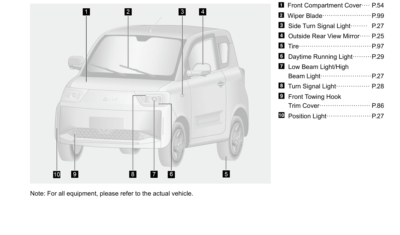
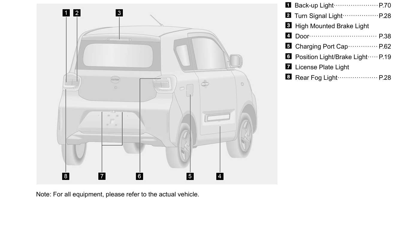
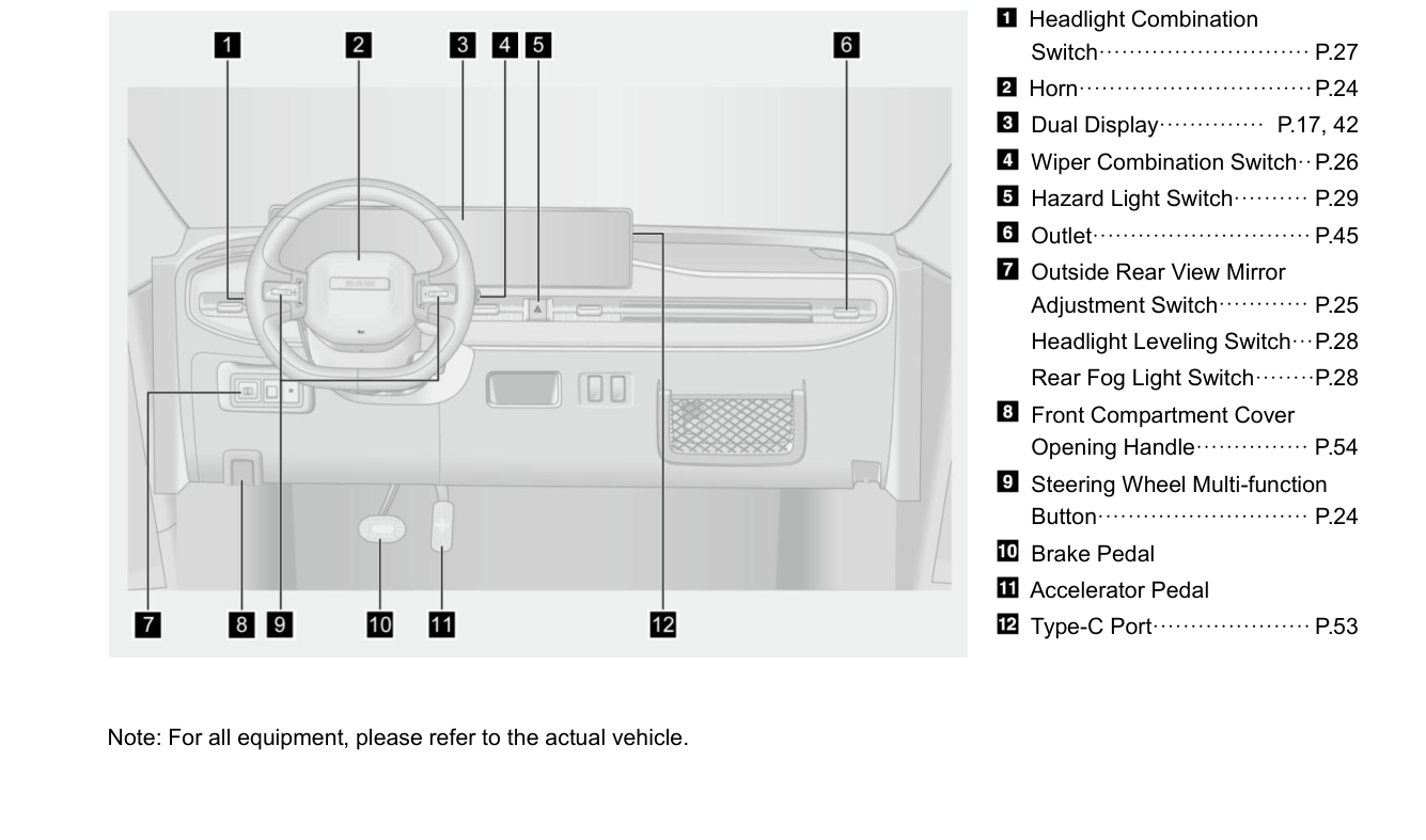
User Notice
Vehicle Equipment
Please note that this manual contains all standard equipment, national standard equipment and special equipment for this series model. Therefore, some equipment or functions described in this manual may not be equipped on your vehicle or are only supplied in certain markets. For detailed configuration information, please refer to relevant sale information or consult your service station at the time of purchase.
Spare Parts and Modifications
It is recommended to use genuine components of Beijing Automobile Works Co.,Ltd. for replacement and installation if replacement is necessary.
Beijing Automobile Works Co.,Ltd. cannot accept any liability nor can it guarantee components which are not genuine BAW products. In addition, vehicle damage and performance problems resulting from the use of non-genuine BAW components may not be covered under warranty.
Do not modify the vehicle in any way, doing so may affect its safety, durability and other performance and violate the limited warranty conditions of the vehicle.
Manual Effectiveness
All contents provided in this manual are current at the time of printing. However, in order to meet the needs of users and technological progress, we reserve the right to make changes (vehicle equipment, product design and technical features) at any time without notice.
New Vehicle Break-in
Due to machining and assembly errors, when using your new vehicle at initial stages, friction resistance between moving parts of a new vehicle is much bigger than normal. New vehicle break-in is mainly to improve the surface quality and friction state of moving parts and extend the service life.
In order to ensure full play to the vehicle performance and reliability in the future, the new vehicle should observe the following precautions for the first break-in 1,000 km:
- Drive on a level ground and avoid driving on muddy or sandy roads during break-in period.
- Generally, driving speed should not be more than 50 km/h.
- Please avoid emergency braking within first 200 km of new car, because the brake cannot provide ideal brake friction at this time, the braking distance during emergency braking is longer than that after break-in. At this time, reduced braking force can be increased by depressing the brake pedal firmly.
- Drive carefully in the first 500 km when starting to use new tires, because the best adhesion at this time is not available.
- After a new vehicle drives for 800 km, tighten wheel nuts again to the specified torque. Also, if wheel has been replaced or wheel nuts have been loosened, tighten wheel nuts again to the specified torque after driving for 800 km.
- When the decelerator is maintained for the first time after performing break-in, the gear oil is required to be replaced.
- After break-in, the drive motor, on-board three-in-one and motor controller are all operating normally.
Prompt Information
Preparation For Driving
Instrument Cluster
Instrument cluster overview (10.25-inch)
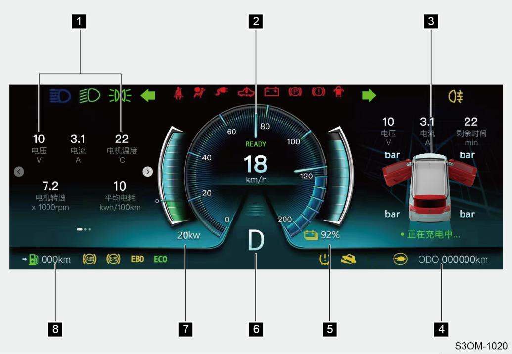
Multi-functional Information

Display Area
Speedometer

Charging Status Information

Odometer

Power Meter

Gear Position Indicator

Drive System Instantaneous

Power Gauge

Remaining Driving Mileage
Multi-functional information display area
It can display multiple screen information, such as voltage, current, motor speed, motor temperature, average power consumption, trip mileage and DTC display, etc. DTC is displayed on the third page of this location if there is a motor or electronic control failure.
Speedometer
Current driving speed (unit: km/h).
Charging status information
When the vehicle is charging, voltage, current, remaining charging time and other contents are displayed.
Odometer
Display total mileage of vehicle.
Power meter
Display remaining charge of power battery. The indication range of power meter is 0 ~ 100. When the first grid of power meter flashes, it indicates that the remaining power battery power is about 10%. At this time, the vehicle speed will gradually decrease, which will cause the vehicle to stop. Please charge the vehicle in time to protect the battery.
Gear position indicator
The current gear position of vehicle is displayed.
Drive system instantaneous power gauge
Display the instantaneous power of drive system as a value and a bar graph percentage.
Remaining driving mileage
The mileage with remaining power is displayed.
Instrument Cluster Adjusting Switch
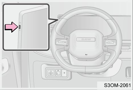
The adjusting button can be used to switch the display mode and reset the trip mileage, and is located on the left side of dual screen. Shortly press once to switch one page, there are 3 pages in total. It can display voltage, current, motor speed, motor temperature, average power consumption, trip mileage and DTC display, etc. To reset the trip mileage, long press the adjustment button for more than 3 seconds in trip mileage display interface on the second page.
Operation/Malfunction Indicator
When turning power switch to ON, some malfunction indicators will come on for a short time, indicating that system is performing self-check. If one system malfunction indicator remains on or flashes after starting the vehicle, please go to the local service station for inspection and repair immediately.
The operation indicator is used to alert driver the operating condition of a certain vehicle’s system, the corresponding operation indicator will come on. Malfunction indicator is used to remind and alert driver that a certain system of the vehicle is malfunctioning, the corresponding malfunction indicator will come on or flash.
| READY indicator |  | After vehicle is started, this indicator comes on, indicating vehicle is ready. |
| Turn signal indicator |  | When the left or right turn signal lights are turned on, the corresponding turn signal indicator flashes. When hazard light switch is turned on, both left and right turn signal indicators will flash simultaneously. |
| Headlight low beam indicator |  | When low beam lights are turned on, this indicator comes on. |
| Headlight high beam indicator |  | When high beam lights are turned on, this indicator comes on. |
| Position indicator |  | When position lights are turned on, this indicator comes on. |
| Rear fog light |  | When rear fog lights are turned on, this indicator comes on. |
| ABS malfunction indicator | 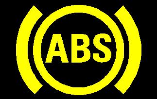 | If this indicator comes on during driving, indicating that ABS system is malfunctioning, please go to the local service station for inspection and repair as soon as possible. |
| Electric Power Steering (EPS) system malfunction indicator |  | If this indicator comes on during driving, indicating that EPS system is malfunctioning. Please contact the local service station for inspection and repair immediately. |
| Electric Brake Force Distribution (EBD) system malfunction indicator |  | If this indicator comes on during driving, indicating that EBD system is malfunctioning. Please contact the local service station for inspection and repair immediately. |
| ECO mode indicator |  | Vehicle starting initial state is ECO mode, this indicator comes on. |
| Abnormal tire pressure malfunction indicator | 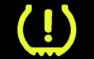 | This indicator is used to alert the driver that tire pressure is improper. Please check if tire pressure is too low or temperature is too high. If tire pressure is normal, please go to the local service station for inspection and repair as soon as possible. |
| Hill hold control system on indicator | 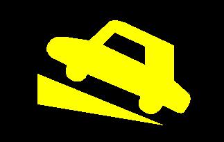 | If this indicator comes on during driving, indicating that hill hold control system is turned on. |
| Communic- ation malfunction indicator |  | If this indicator comes on during driving, indicating that vehicle communication system may be malfunctioning, please go to the local service station for inspection and repair as soon as possible. |
| Drive system power limitation indicator |  | If this indicator comes on during driving, indicating that drive system may be malfunctioning, please go to the local service station for inspection and repair as soon as possible. |
| Battery power indicator |  | If the indicator comes on, it indicates that the remaining power of power battery is less than 20%. Please arrange your trip reasonably. |
| Battery power indicator |  | If the indicator comes on, it indicates that the remaining power of power battery is less than 10%. Please charge in time. |
| Seat belt unfastened warning light |  | This indicator is used to alert the driver that the seat belt is not buckled or fastened firmly. Check that seat belt is fastened firmly and drive safely. |
| Charging cable connection indicator |  | This indicator comes on during charging, indicating that charging cable is connected. If this indicator does not come on during charging, please check if each connector of charging cable is connected reliably. |
| Vehicle system malfunction warning light |  | If this warning light comes on, it indicates that the vehicle system is malfunctioning. Please contact the local service station for inspection and repair immediately. |
| DC malfunction indicator |  | If this indicator comes on during driving, indicating that DC system is malfunctioning, please go to the local service station for inspection and repair as soon as possible. |
| Parking brake indicator |  | After applying parking brake, this indicator comes on. After releasing parking brake, this indicator goes off. |
| Electronic brake force distribution system malfunction indicator/Lo w brake fluid level malfunction indicator |  | This indicator is used to alert the driver that brake fluid level is low or electronic brake force distribution system is malfunctioning. Please check the brake fluid level or go to the local service station for inspection and repair. |
| Door open indicator |  | When any door is opened, the indicator comes on. After the door is closed, the indicator turns off. |
Steering Wheel
Horn
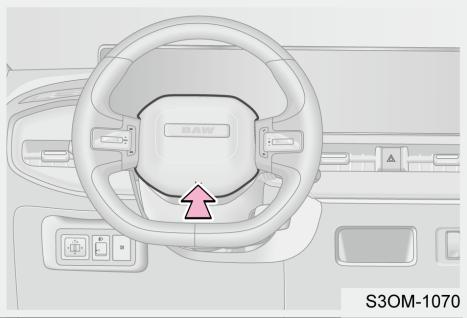
To sound the horn, press center area of the steering wheel.
Steering Wheel Buttons (If Equipped)
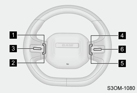

Press the button to switch to previous track

Press the button to switch to next track.

Press the roller to switch modes. Push the roller up to fast rewind, and push the roller down to fast forward.

Answer the call.

Hang up the call.

Turn the roller to adjust the volume; Push the roller to mute the audio system.
Rear View Mirror
Inside Rear View Mirror
Adjusting inside rear view mirror position
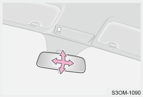
Manually adjust inside rear view mirror to a proper position before driving, to make sure that driver can achieve an optimum view.
Glare-resistant function
By operating the control lever, the reflected light from the headlights of vehicles behind can be reduced
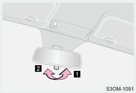
Manually adjust inside rear view mirror to a proper position before driving, to make sure that driver can achieve an optimum view.
When encountering the high beam of rear vehicle, move the control lever forward or backward to adjust the reflection angle of rear view mirror. The glare-resistant effect is achieved by changing the reflection angle.
Outside Rear View Mirror
Adjusting outside rear view mirror manually (if equipped)
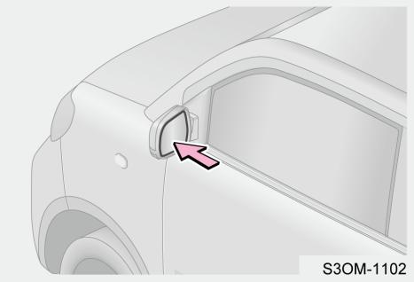
Press the edge of lens by hand to adjust to a suitable visual field.
Adjusting outside rear view mirror electrically (if equipped)
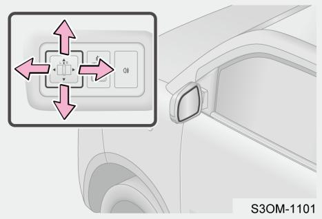
Operate the control lever to select the mirror to be adjusted (“L”: left side, “R”: right side). Operate the control button to adjust the rear view mirror lens up and down or inside and outside. After adjustment, reset the control lever to the middle position.
Folding outside rear view mirror
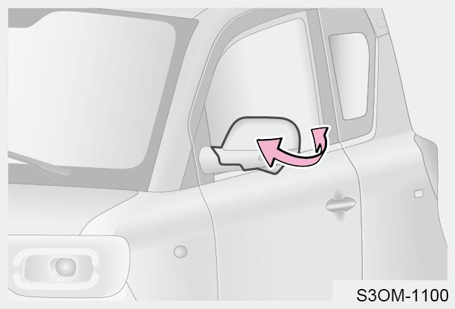
Push the rear view mirror forwards or backwards to fold outside rear view mirror.
Wiper System
Wiper Operation
Wiper combination switch
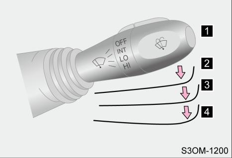
Turn power switch to ON, move wiper combination switch:
OFF: Turn off front windshield wiper
INT: Intermittent wiping

LO: Low speed wiping

HI: High speed wiping
Front washer operation
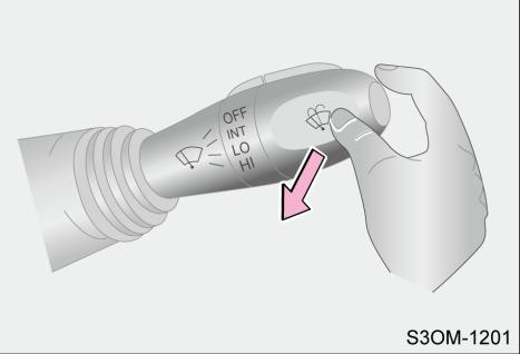
Turn power switch to ON, pull wiper combination switch towards the steering wheel and hold, the front washer sprays water, and front wiper operates simultaneously. Front washer will stop operating when the switch is released, the wiper will wipe 3 cycles at low speed.
Lighting System
Exterior Lighting
Headlight combination switch
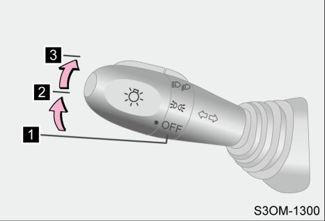
Turn power switch to ON, rotate headlight combination switch: OFF: Turn off headlight.

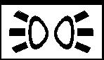 : Turn on position lights,
 license lights and backlights.

 : Turn on low beam lights and all above lights.
Headlight high beam
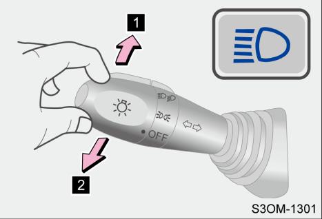
Push headlight combination switch  away from yourself to turn on high beam light. Pull the switch to the original position to turn off high beam light.
Pull the control handle to yourself  and then release, the high beam light flashes once.
Leveling headlight beam
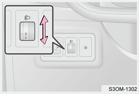
After turning on headlight, headlight beam leveling (levels 0 - 3) can be adjusted according to the number of passengers and vehicle load. The higher the value, the higher the beam level.
Turn signal light
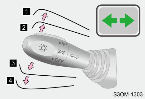
Right turn

Change lane to right (Pull the control lever to the halfway position and release it)
Change lane to left (Pull the control  lever to the halfway position and release it)
Left turn
Rear fog light
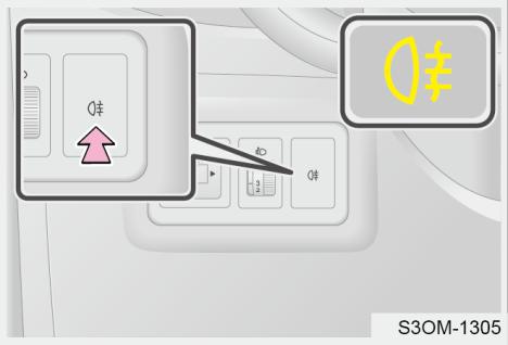
When the low beam lights of headlight are on, press rear fog light switch on the instrument panel switch to turn on rear fog light, rear fog indicator on instrument cluster will come on.
Press rear fog light switch again to turn off the rear fog light, rear fog indicator on instrument cluster will turn off.
Daytime running light
When the vehicle is in READY, daytime running lights come on. When position lights or low beam lights turn on, daytime running lights turn off.
Brake light
Depress the brake pedal, brake light and high mounted brake light turn on.
Back-up light
Turn power switch to ON, shift gear position to R, back-up light turns on.
Hazard light
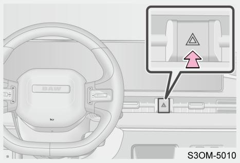
Press hazard light switch, turn signal lights flash and the turn signal indicator on instrument cluster flashes at the same time; press the switch again, turn signal lights and indicator will turn off.
In case of vehicle failure or traffic accident etc., please turn on the hazard lights to warn other vehicles to avoid the secondary accident.
Interior Lighting
Front interior light
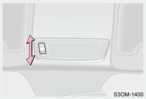
ON: Turn on the front interior light.
OFF: Turn off front interior light.
DOOR: When any door or back door is opened, the front interior light will turn off after coming on for 30 seconds. When it is turned on, if the power switch is turned to ON and all doors are closed, interior light goes off immediately; When it is turned on, if the power switch is not turned to ON and all doors are closed, interior light goes off after 15 seconds.
Seat
Correct Sitting Posture
The seats, head restraints, seat belts are helpful to protect passengers. Using them adequately will provide you with more protection.
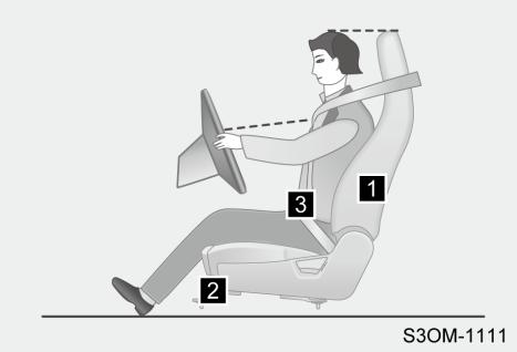
Adjust seatback angle so that you can sit up straightly, it is not necessary to tilt the body forward.
Adjust seat so that you can fully depress the pedal, hold the steering wheel with slightly bent arms.
Fasten seat belt properly.
Front Seat
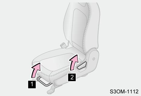
Forward and backward adjustment grip for seat position
Seatback angle adjustment grip

The front seat position is designed slide 180 mm forward and 10 mm backward, and the seatback angle is designed to be adjustable within 25°.
Seat Belt
Using Seat Belt Correctly
Before driving, ensure that all occupants wear their seat belt properly.
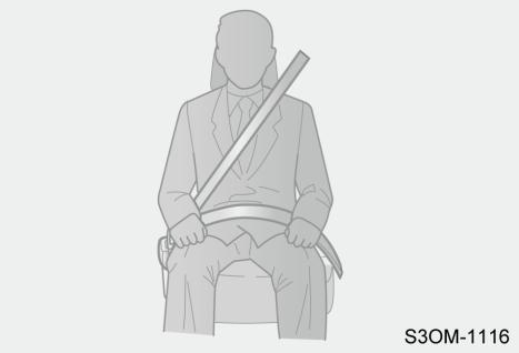
- Extend the shoulder belt so that it can across the entire shoulder, but does not come into contact with the neck or slide off the shoulder.
- Position the lap belt as low as possible over the hips.
- Adjusting the seatback position. Sit up straightly and well back in the seat.
- Do not twist the seat belt.
Fastening and Releasing Seat Belt
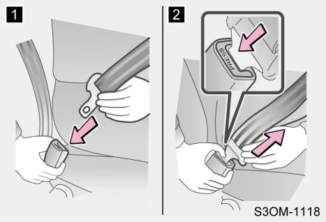
Fastening seat belt
Push the tab into the buckle until a click sound is heard.
Releasing seat belt

Press release button.
Seat Belt Precautions
When there is any child in vehicle
Do not allow child to play with the seat belt. If a seat belt twists around a child’s neck, it may cause chocking, other serious injuries or even death. If this occurs and the buckle cannot be released, scissors should be used to cut the belt.
Pregnant woman
Please follow the doctor's advice and fasten seat belt properly.
Women who are pregnant should position the lap belt as low as possible over the hips in the same manner as other occupants. Extend the shoulder belt completely over the shoulder, and avoid belt contact with the rounding of the abdominal area.
If the belt is not fastened properly, not only the pregnant woman, but also the fetus could suffer serious injury or even death as a result of sudden braking or a collision.
Damage and wear of seat belt
- Ensure that the belt and the tab are locked and the belt is not twisted.
- Do not let the door catch the seat belt, tab or buckle, otherwise the seat belt may be damaged.
- Check the seat belt device regularly. Check components of seat belt for cuts, fraying and loose parts. Do not use damaged seat belt and replace it. A damaged seat belt cannot protect occupant from serious injury or even death.
- If your vehicle has been involved in a serious accident, even if seat belt is not obviously damaged, you should go to the local service station for inspection and repair.
- Do not attempt to install, remove, modify, disassemble or dispose of the seat belts. Please contact the local service station for necessary repair.
Child Safety Information
Be sure to observe the following precautions when there is any child in vehicle. Use a child restraint system appropriate for the child, until the child becomes large enough to properly wear the vehicle seat belt.
Do not allow child to operate the equipment that may clamp body parts (such as power window, front compartment cover, back door, seat, etc.)
Interior Function
Key Information
Keys
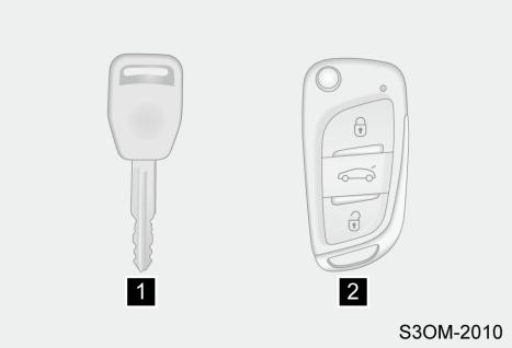

Mechanical key

Remote control key
Every new vehicle is equipped with two keys, keep one as a spare.
For safety, please keep the number plate of the key in a safe place to prevent others from illegally preparing the key.
Wireless remote control
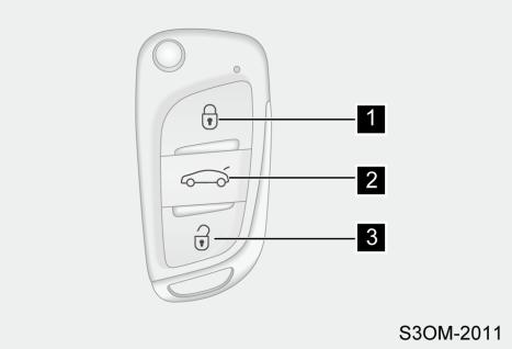

Lock button

Back door opener button

Unlock button
Using mechanical key
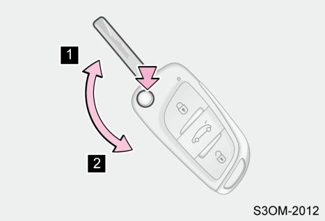

Releasing
Press the button to release the key.

Folding
Press and hold the button while folding the key into the retainer.
Function limit
- The battery may be depleted even if the remote control key is left idle. The following symptoms indicate that the remote control key battery is low or may be depleted. If necessary, replace with new battery.
- The wireless remote control function does not work.
- The LED indicator on the surface of the key does not come on.
- The operating range of the wireless remote control function may be reduced.
- Prevent damage to keys
- Do not disassemble the key.
- Do not drop the key, avoid strong collision or bending.
- Do not expose the key to high temperature for a long time.
- Do not paste adhesive stickers or other items on the key surface.
- Do not wet keys or wash in equipment such as ultrasonic cleaners.
- Do not attach metal or magnetic substances to keys or place keys near such substances.
- The wireless remote control function may not work properly in the following conditions
- When the wireless remote control key battery may run out.
- When it is near a TV tower, electric power plant, gas station, radio station, large display, airport or other facility that generates strong radio waves or electrical noise.
- When carrying portable radio, cellular phone, or other wireless communication devices.
- When there is more than one wireless remote control key nearby.
- When a metal object is touching or covering wireless remote control key.
- When other wireless remote control keys (that emit radio waves) are being used nearby.
- When wireless remote control key is placed near an electrical device (such as personal computer).
- When there is a window film or metal object with metal content adhering to the window
Replacing key battery
There is a lithium battery in the remote control key, which can generally be used for 2 years. When the remote control distance is gradually shortened (you must get closer to the vehicle for successful remote control), it indicates that the battery is low. The battery in the key cannot be charged. When the battery is depleted, it is recommended to replace the battery at the local service station.
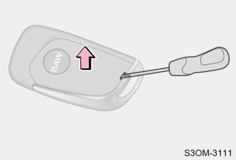
Step 1: Remove the key cover
Use a screwdriver with its tip wrapped with tape or similar tool, insert it into the removal hole of key back cover, and slowly pry the key back cover to separate it.
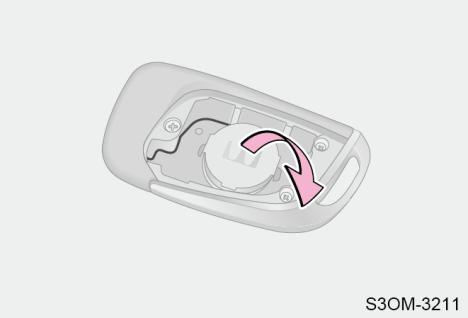
Step 2: Flip the remote control key in the opposite direction to make its control module slide out slowly.
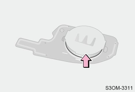
Step 3: Remove old battery on control module, install the new battery (+ faces upward).
Vehicle Anti-theft System
When the system detects a forcible entry, it will sound an alarm and keep the hazard lights flashing.
After all occupants get off the vehicle, close all doors and back doors and lock all doors by the lock button on the key, at this time the vehicle anti-theft system is activated.
Alarm
Alerts can be triggered when:
Open a locked door or back door.
Deactivating or stopping the alarm
Operate any of the following to deactivate or stop the alarm:
- Use the wireless remote control to unlock the door.
- Open the door with mechanical key. Turn the power switch to ACC or ON.
- Without any operation, the alarm will automatically terminate after about 30 seconds and the anti-theft mode will be re-entered.
Doors
Locking and Unlocking Doors from Outside the Vehicle
Wireless remote control
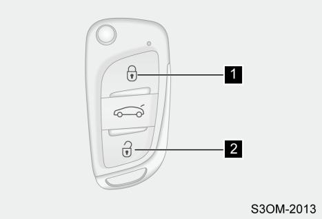

Locking doors
When the power switch is turned to OFF and all doors and back door are closed, press this button to lock all doors. Check that the doors are securely locked.
When any door or back door is not closed, the door cannot be locked by pressing this button.

Unlocking doors
Mechanical key
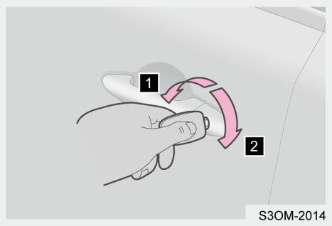
Locking doors
Unlocking doors
Auto locking
The vehicle will be automatically locked when all doors are closed and the vehicle speed exceeds 20 km/h. When a valid collision signal is received, the vehicle is unlocked.
Safety function
If the door or back door is not opened within about 50 seconds after unlocking the doors using the wireless remote control, the safety function automatically locks the vehicle again.
Auto unlocking function
When the vehicle is locked, the doors are automatically unlocked if the power switch is turned off.
Locking and Unlocking Doors from Inside the Vehicle
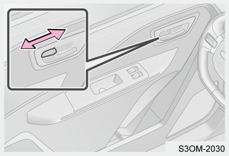
Pull the lock button backward to  unlock doors
Pull the lock button forward to lock  doors
Windows
Power Windows
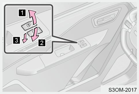
Operate power window switch after power switch is turned to ON: Long press to rise window  manually
Long press to lower window  manually
Short press to lower window  automatically*1
*1 When the window is moving, operate the switch again to stop the window in halfway position.
Remote control window down function
When the power switch is turned off, all doors are closed. In the effective area, long press the unlock button on the remote control key to open all windows. Long press the lock button on the remote key to close all windows.
Air Conditioning System
Air Conditioning Control Panel
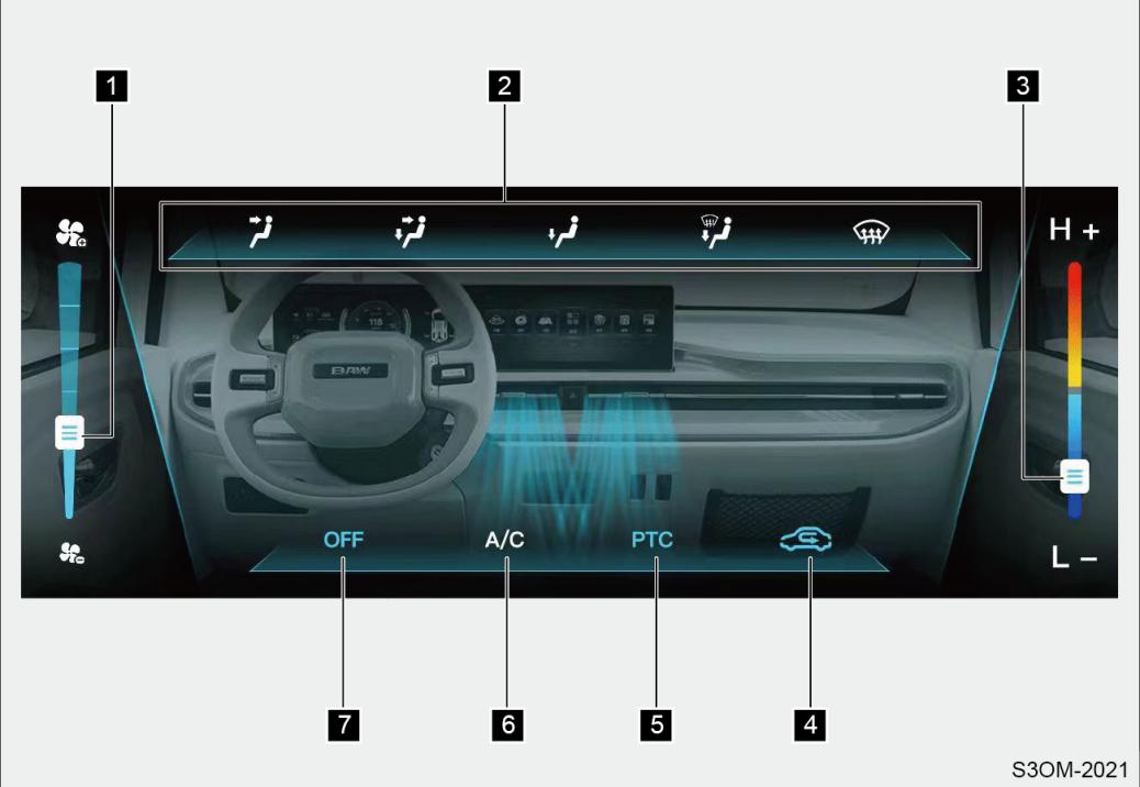

Airflow volume adjustment touch button

Outlet mode selection touch button

Temperature adjustment touch button

Outside/recirculated air mode touch button

Vehicle heater switch

A/C touch button

A/C OFF touch button
Air Conditioning Operation
Airflow volume adjustment
It is divided into level 0 - 6 from the bottom to the top, level 0 can not vent, level 6 is the maximum air volume.
Temperature adjustment
Cooling and heating modes are divided into 3 levels respectively, the temperature is adjusted from the low temperature to the high temperature by dragging the touch button according to different needs.
Outside/recirculated air mode
Press outside/recirculated air mode touch button, switch between recirculated air mode and outside air mode.
Vehicle heater (PTC heating)
Press the vehicle heater switch, that is PTC touch button, to turn on A/C heating mode.
Outlet mode selecting
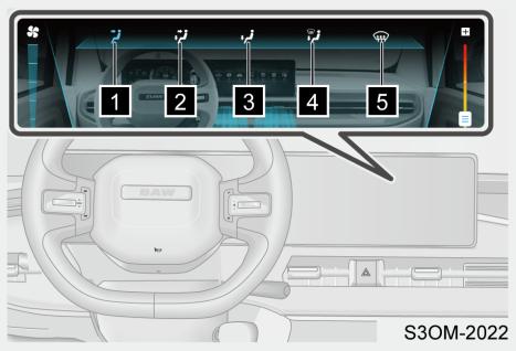
Turn the power switch to ON. After clicking outlet mode selection touch button, the icon will turn on, and enter corresponding mode of air outlet.

Air flows to face.
Air flows to face and feet.

Air flows to feet.

Air flows to feet and windshield.

Air flows to windshield
Outlet
Position of air outlets
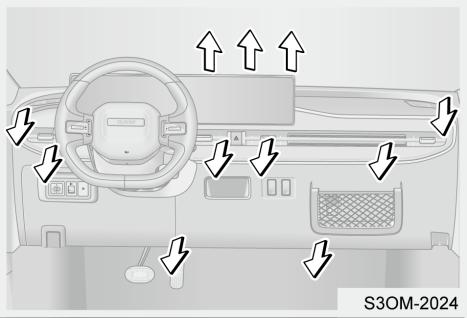
The air outlets and air volume changes according to the selected airflow mode.
Adjustment of air outlets
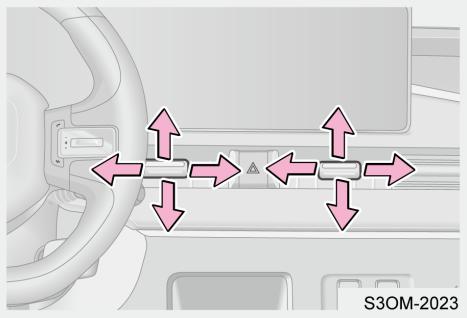
Direct airflow to left or right, up or down, or move the adjusting plate laterally until the air outlet is completely closed or opened.
Audio System
Audio system overview (10.25-inch)
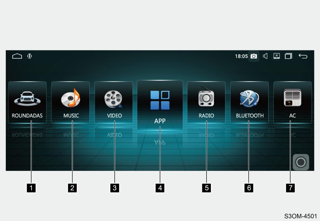
Enter roundadas

Enter music playing interface


Enter video playing interface

Enter App interface

Enter radio interface

Enter Bluetooth interface

Enter AC adjustment interface
It can display multiple screen information and support multi-touch zoom in/out. It supports sound effect adjustment, radio, local music playing, KUWO music, reversing view monitor, Bluetooth connection, making calls, air conditioning system operation display, roundadas, multifunctional steering wheel control volume adjustment.
Pull-down status bar
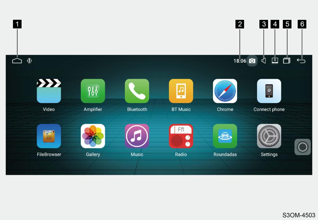
Click any screen to return to main  interface
Current system time of head unit


Volume icon
Turn off screen display

Click to open the recently running procedure
Return to the previous menu
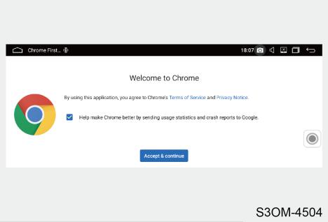
Browser
After the head unit is connected to network, open the browser and enter the relevant URL to browse the relevant websites; the third party application can be download through website.
Music equalizer
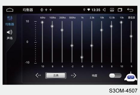
Equalizer: Play mode of sound quality in different modes: There are six modes including normal/classic/ popular/rock/jazz/custom.
Sound field: There are five modes including driving mode/whole vehicle mode/front vehicle mode/rear vehicle mode/user mode, the whole vehicle mode is the default mode.
KUWO music
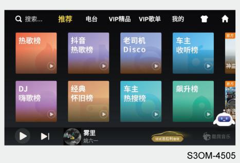
After the head unit is connected to network, you can search for on-line music to play.
Bluetooth phone
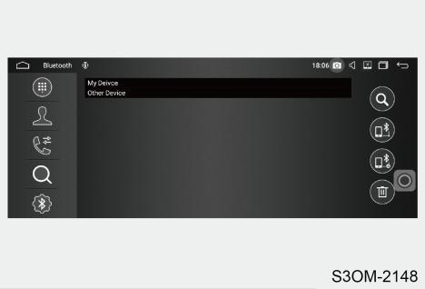
When Bluetooth is not connected, click to enter the Bluetooth setting interface; when Bluetooth is connected, click to enter the dialing interface.
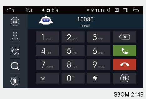
Bluetooth phone contacts, call history and favorite contacts can be checked.
Bluetooth music
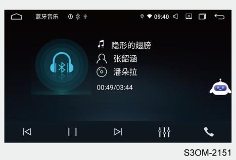
After the head unit is connected to mobile phone Bluetooth, music and radio etc. on the mobile phone can be played.
Settings
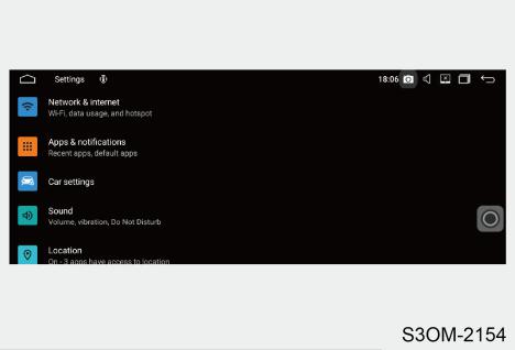
The relevant settings and menus of the head unit system;
- Apps & notifications: Check the operating status of each App;
- Car settings:
- Personal setting: Low voltage protection is 11.5 V by default, and is used for 360° parking monitoring. It is recommended that the battery voltage is higher than 11.5 V.
- Driving setting: Reversing volume has three options, ON/50%/OFF, and the default is 50%, which means that the audio/video volume is reduced to 50% of normal when reversing.
- Factory setting: (This item is not open for user operation).
- Upgrading and restoring default setting: The head unit system and MCU version can be upgraded manually through USB disk, and the head unit can also be restored to factory setting.
Music playing
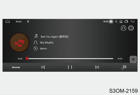
The player can play the local music and music of external USB disk. Slide to the left to see the list of all audios, and slide to the right to see the music list that is played currently; the formats of music can be played: mp3, wav, mpa, mp2, m1a, m2a, ogg, m4a, mka, ac3, wma, ape and flac.
Video playing
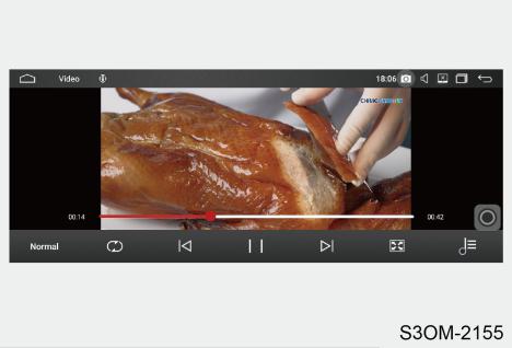
The local video files of the head unit and all video files in Type-C can be played. Slide to the left to see the list of all videos, and slide to the right to see the video list; The formats of video can be played: avi, wmv, asf, mpg, mpeg, mpe, m1v, m2v, mpv2, ts, vob, ogm, ogv, mp4, m4v, m4p, m4b, mkv, rm, ram, rmvb, flv, swf and mov.
Radio
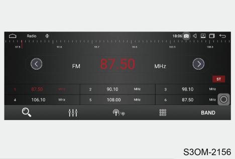
Connect the original radio antenna to receive the local radio stations.
- The radio includes FM and AM, click BAND at the lower right corner for switching;
- Click search icon to search and save radio stations automatically; you can also click to perform fine tune search; and can also drag the progress bar to search radio stations manually, and the relevant radio stations can be saved by long pressing 6 bands below the menu;
- Click to save to personal favorites; and click to view the favorite list;
Gallery
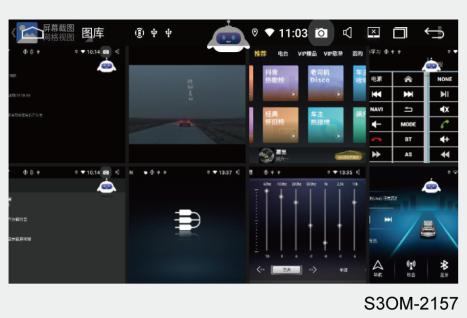
You can view images in Type-C; You can perform operations, such as deletion, slide show, editing, left/right rotation, cropping, setting photo to as well as viewing detailed information, etc.
File management
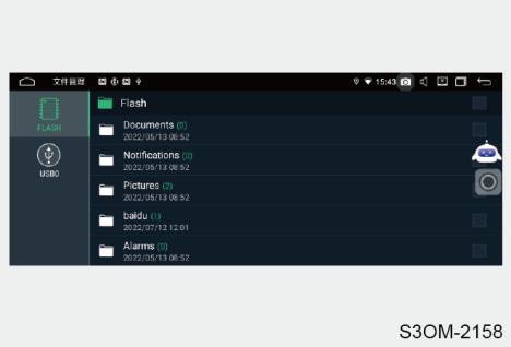
- Flash, local folder directory.
- Type-C1, external USB flash disk, which is usually used to play files in USB flash disk.
Storage Space
Door storage boxes
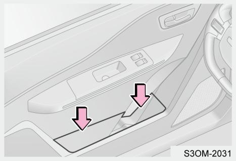
There are door storage boxes on the left and right doors.
It can be used to place debris such as bottles or cloth.
When storing a bottle, please tighten the bottle cap. Bottles may not be stored due to their size or shape.
Instrument panel center storage box and net pocket
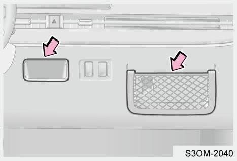
Instrument panel center storage box and net pocket can store some small items.
Cup holder
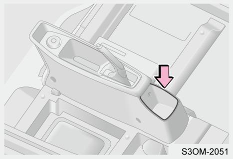
The cup holder is located on lower rear part of auxiliary fascia console.
Power Outlet
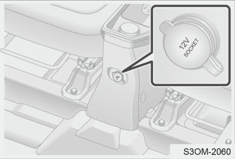
Front power outlet is located on lower front part of auxiliary fascia console. This socket can be used to provide power to 12 V electrical appliances.
When the power switch is turned to ON, it can be used.
Type-C Interface
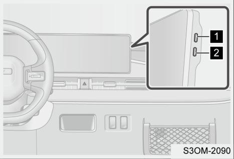
The Type-C interface is located on the right side of audio screen. When the power switch is turned to ON, it can be used.
Only slow charging can be performed.
It can be used to read the data in the Type-C connector and perform slow charging.
Sun Visor
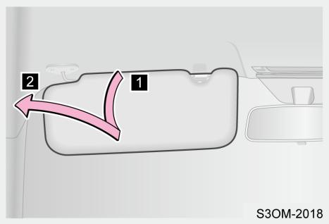
Front position

Flip the sun visor down. Side position
Flip the sun visor down, disengage the hook, and pull to the side.
Hook
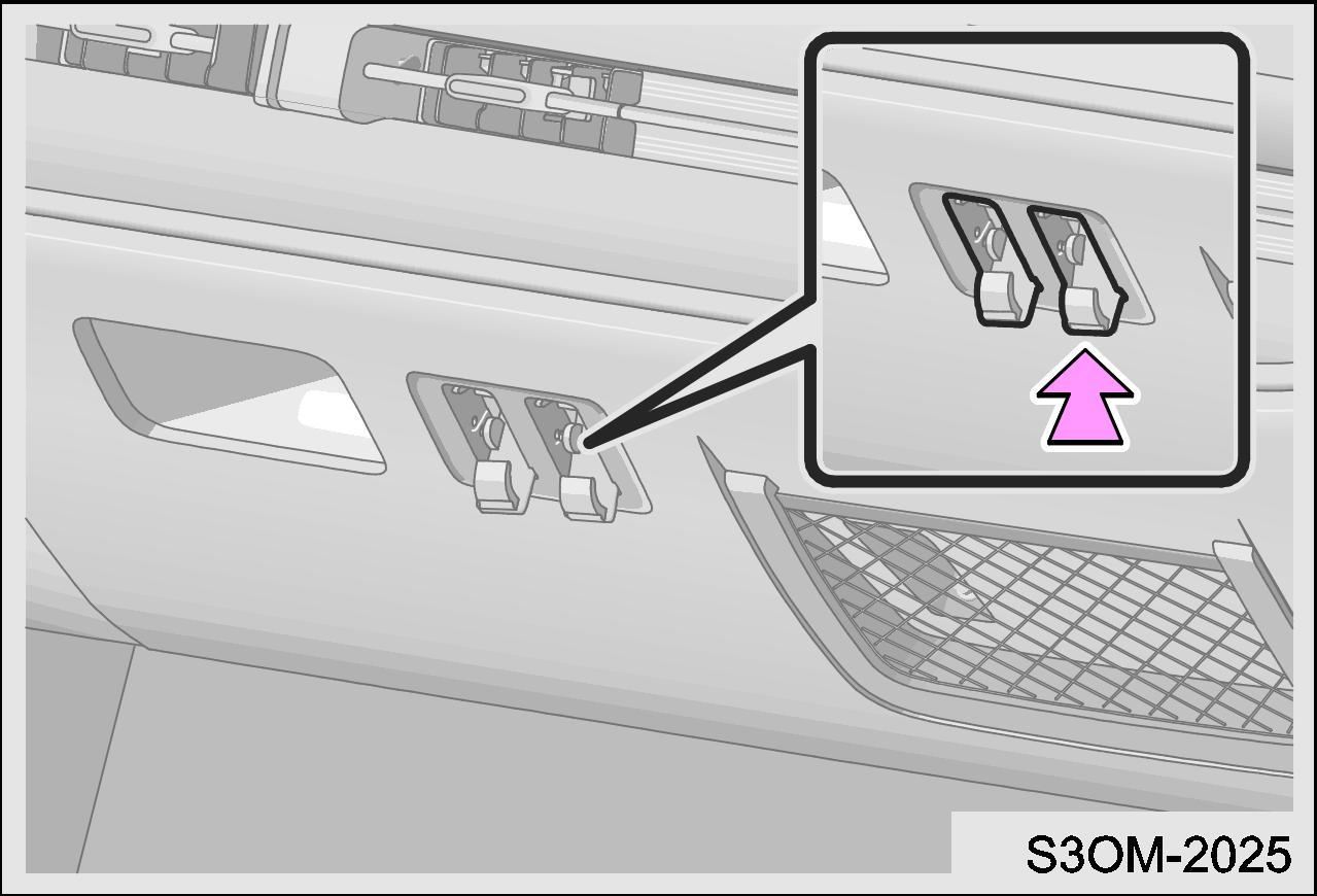
The hook can be used by pressing the lower edge.
It is used to hang some light items.
Front Compartment Cover
Opening Front Compartment Cover
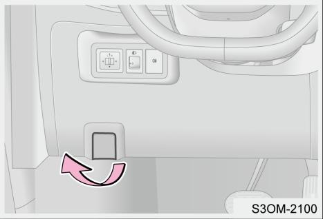
Step 1: The front compartment cover will pop up slightly by pulling front compartment cover opening handle on the lower left side of the instrument panel.
Step 2: Reach your hand under the front edge of the front compartment cover, pull up on the unlocking handle and fully open the front compartment cover.
Step 3: Firmly insert the support rod into the support rod seat to keep front compartment cover opening.
Closing Front Compartment Cover
Step 1: Check the area under front compartment cover to ensure that the covers of all containers are in place and all scattered objects (such as tools, etc.) have been removed.
Step 2: Fix the support rod in the clip.
Step 3: Lower the front compartment cover with a slight force, check that front compartment cover is fully closed and locked.
Back Door
Opening/Closing Back Door
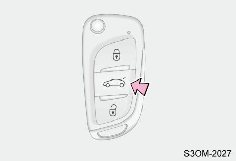
Long press back door opener button on remote control key for 2 seconds and back door will be unlocked.
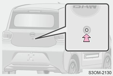
When the vehicle is unlocked, press back door opener switch on the back door and open back door manually.
To close the back door, press the back door from outside of the vehicle to make sure it is fully closed.
Driving Vehicle
High Voltage Safety
High voltage system components mainly include power battery assembly, on-board three-in-one, high voltage cable, motor controller, drive motor, compressor and heater core (PTC) etc.
- Orange cable in vehicle is high voltage component cable and connector. Do not touch exposed or damaged orange high voltage cable, otherwise resulting in electric shock.
- High voltage warning label is attached to high voltage component, please pay attention to relevant warnings. Do not touch high voltage component, high voltage cable and its connector to avoid electric shock injury.
Meanings of high voltage sign
| Sign | Meaning |
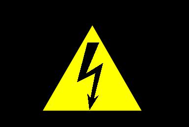 | High voltage, dangerous! |
 | Pay attention to safety |
Usage Precautions for Electric Vehicle
The vehicle is a pure electric vehicle, in order to ensure your safety and you can better understand and use pure electric vehicle, please observe the following suggestion during use:
- When cleaning vehicles or in rainy days, close the doors, front compartment cover, back door to avoid water directly wet high voltage system and power battery, so as to avoid short circuit of high voltage system.
- When it is hot in summer, it is not recommended to expose vehicle in high temperature for a long time and it is better to park vehicle in a well-ventilated and cool place.
- When it is used in winter, the charging efficiency of power battery decreases. It is recommended to charge vehicle as soon as possible after driving in winter to avoid the decrease of battery temperature, resulting in charging for a long time and affecting the use.
- With the increase of service life and charging times, personal driving habits, road conditions, environment and other factors, the capacity of power battery may decline to a certain extent, resulting in decrease of driving mileage, which is normal.
- When vehicle drives in low temperature, because discharging capacity of the battery will be reduced, the power performance and driving range of the vehicle will be reduced, and it can be recovered after the temperature rises.
- Because the service life of power battery is related with discharge depth, avoid deep discharging from power battery. When the vehicle is prompted to charge or stop using, charging should be performed timely to protect the cycle service life of the power battery.
- Sudden acceleration will sharply increase discharging of the power battery during driving, which is not conducive to the use of power battery. It is recommended to keep slow acceleration as far as possible, which can significantly improve driving mileage and service life.
- It is recommended to use slow charging to charge the vehicle fully for the first time, and use slow charging for 100% charging at least half a month, which is helpful to correct battery residual power/driving mileage and increase service life of the power battery.
- If vehicle is parked for a long time, keep the capacity of power battery between 50% and 70%, and disconnect negative cable from 12 V battery.
- When power battery of vehicle touches the ground, vehicle is collided or soaked in water, serious malfunction alarms (such as power battery over temperature, insulation alarm, etc.) are displayed on instrument cluster and power battery case and connector are deformed or cracked seriously, please contact the local service station for inspection and repair immediately.
Charging Vehicle
Charging Information
When does the vehicle need to be charged
- It is recommended to charge and discharge the battery of new vehicle for maintenance, first discharge to about 20% of soc, and then charge to ensure that the soc displays 100% after the first charging.
- If low-battery warning light comes on during driving, it indicates that power battery is low and needs to be charged as soon as possible.
- Charging must be performed when power meter indicates residual power is low or driving mileage cannot meet the travel needs.
Charging precautions
During charging or at the end of charging, please pay attention to the following safety precautions to avoid high voltage electric shock or more serious injuries.
- If you have been transplanted a cardiac pacemaker or cardiovascular defibrillator, do not stay in the vehicle for a long time when charging the vehicle, otherwise it may effect the function of the electronic medical device and cause personal injuries.
- Please perform charging in a ventilated environment far away from liquid and fire source. It is recommended that ambient temperature is between 0 and 35℃ when charging vehicle, and avoid charging in low or high temperature environment (it is recommended to charge at the noon in winter, in the morning and evening in summer).
- Make sure to wipe off water or dirt around the charging port of the vehicle before charging, then open the charging port for charging. Pay special attention to whether there is no residual water on charging socket and it adjacent area.
- Make sure that there is no water, other objects, rust or corrosion on charging interface or charging plug. If there is water or rust on charging interface or charging plug, do not charge to avoid short circuit or electric shock, even personal injuries.
- Before charging, check that power outlet is in good condition, internal earth wire grounding is normal, and the contact coppers of live wire, neutral wire and earth wire are free of ablation, looseness or poor contact. Doing so can cause the vehicle charging malfunction.
- Before charging, check if the charging cable surface or shell is damaged. If the above conditions occur, please contact the local service station for repair or replacement. Do not use the damaged charging cable.
- Before charging, confirm that the parking brake is applied and the vehicle cannot move.
- Do not touch the metal parts of charging interface and charging socket during charging. If sparks are generated on vehicle or on-board three-in-one, do not touch vehicle and any part, otherwise, it may cause electric shock and personal injuries.
- Make sure charging cable is in natural state and do not hang it in air during charging.
- If there is special smell or smoke in vehicle, cut off power supply safely and immediately and contact the local service station in time.
- In case of heavy rain, lightning, heavy snow, hail and other weather conditions, do not touch charging interface during charging and the end of charging to avoid personal injuries caused by electric shock.
- After charging is completed, hold the insulation part to operate when unplugging the charging plug, and do not pull or drag charging cable directly.
- After charging is finished, make sure that charging interface protective cover and charging port cover are closed, and confirm that charging plug has been unplugged from charging port before starting vehicle.
Charging Method
Charging with household AC power
- Start charging
Step 1: Park vehicle in AC charging area, turn off power switch, remove key and apply the parking brake. Step 2: Remove charging cable and check if cable is in good condition.
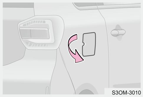
Step 3: Pull the protruding area on edge of charging port cover to open the charging port cover.
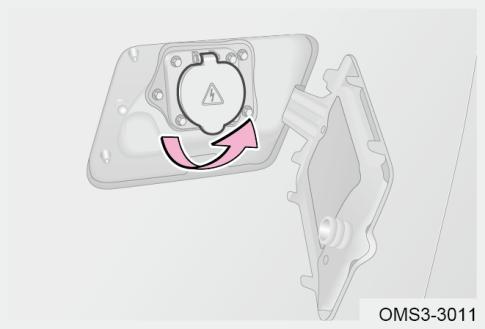
Step 4: Open charging socket protective cover.
Step 5: Press release button and remove charging gun protective cover.
Step 6: Connect charging gun to vehicle socket, and charging gun locks until a click sound is heard.
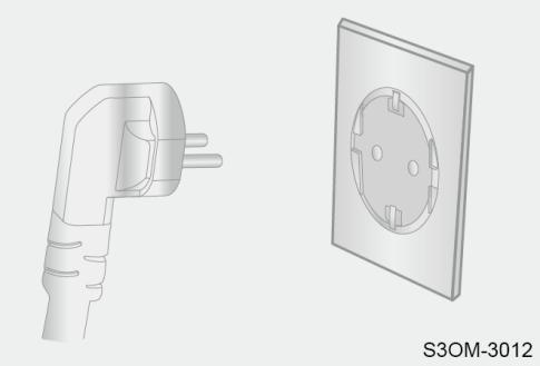
Step 7: Connect power supply plug to power supply socket.
- Stop charging
Step 1: Unplug power supply plug from power supply socket and keep charging cable properly.
Step 2: Press release button and unplug charging gun.
Step 3: Close charging socket protective cover, then close charging port cover.
- Description of indicators on control box
| Operating Condition | Indicator Condition | ||
| Connecting Indicator (Blue) | Charging Indicator (Green) | Malfunction Indicator (Red) | |
| Initial state | (Blue - green - blue - red) lights - go off, flash in order for 1 second | ||
| Wait for connection | Remain on | Off | Off |
| Normal plug-in charging gun | Flash | Off | Off |
| Normal charging | Off | Flash (breathing) | Off |
| Charging completed | Off | Remain on | Off |
| Malfunction table | |||
| Ungrounded malfunction | Off | Off | Remain on |
| Powered on self-check failure | Red light comes on once and stops for 3 seconds, and cycles | ||
| Abnormal CP communication signal | Red light comes on 2 times and stops for 3 seconds, and cycles | ||
| Overvoltage/undervoltage protection | Red light comes on 3 times and stops for 3 seconds, and cycles | ||
| Overcurrent malfunction | Red light comes on 4 times and stops for 3 seconds, and cycles | ||
| Leakage protection | Red light comes on 5 times and stops for 3 seconds, and cycles | ||
| Temperature control board over temperature | Red light comes on 6 times and stops for 3 seconds, and cycles | ||
Charging with AC charging pile
Step 1: After vehicle stops steadily and safely and the parking brake is applied, turn off the vehicle power.
Step 2: Pull the protruding area on edge of charging port cover to open the charging port cover.
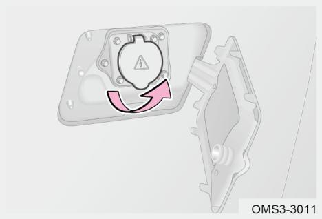
Step 3: Open charging socket protective cover.
Step 4: Remove charging gun from charging pile and insert it to AC charging port. Please confirm that the charging gun is completely inserted.
Step 5: Charging will be started after payment according to operation instructions on charging pile, and confirm that the vehicle is charged normally.
Step 6: After charging is finished, pull out charging gun correctly and cover charging stand protective cover and charging port cover.
Step 7: Insert charging gun into charging pile correctly.
Power Battery
Power battery which is located under vehicle chassis provides driving power for vehicle.
In winter, discharging performance of power battery will decrease with the decrease of the temperature, and the performance can be recovered with the increase of the temperature. It is recommended to avoid rapid acceleration and high speed driving for a long time when driving at low temperature in winter, reasonably arrange the usage of air conditioning heating and charge the vehicle in time.
If it is necessary to replace power battery, be sure to hand over used battery to recycling service stations designated by the local service station for recycling. Discarding power battery carelessly will pollute the environment and even cause personal injuries. Relevant regulations also require that this kind of waste should be disposed.
- If power battery is not handled properly, it may lead to serious accidents, resulting in power battery damage or personal injuries. In order to avoid accidents, pay attention to the following precautions:
- Do not expose the vehicle to the environment over 45 ℃ for more than 24 hours, and park vehicle in cool environment in time.
- Vehicle can be used only when the vehicle is charged and heated for maintenance in a low temperature (lower than -20℃).
Power battery recovery
When power battery needs to be repaired or replaced, the vehicle should be transported to after-sales organization with corresponding capacity. When the vehicle meets disposal requirement, it should be transported to the disposed vehicle recycling and disassembly company, and hand over the used power battery to recycling service stations. If the used power battery is handed over to other units or individuals, the vehicle owner should be responsible for environmental pollution or safety accidents caused by removal or disassembly of the power battery without permission.
Inspection Before Driving
In order to ensure the safety of yourself, all passengers and other users on roads, be sure to check following items before driving each time:
Inspection Before Entering Vehicle
- Check and remove snow, leaves, etc. on the body.
- Check if tire is worn excessively, tire inflation pressure is normal and foreign matter is embedded in tread pattern.
- Check if front compartment cover and charging port cover are closed and locked.
- Check if all windows and rear view mirror are clean.
- Check if there is any obstacle around the vehicle.
Inspection After Entering Vehicle
- Check if all doors are fully closed.
- Check and clean unfixed objects on the instrument panel.
- Adjust seat position and make sure the seat is locked.
- Check that all passengers fasten seat belts. If the passengers include children, please make sure that children restraint system is used properly.
- Check if the view from each angle is clear and good (front view, side door view, rear view mirror view).
Inspection After Starting Vehicle
- Check if illumination light, turn signal light, brake light and other functions are normal.
- Check if residual power of power battery and driving mileage, ensure that vehicle can reach the destination successfully.
- Check if each pedal can be depressed smoothly. If you need lay floor mat, please choose proper floor mat. The improper shape of floor mat, improper laying position or double-layer laying will effect the pedal operation, causing the vehicle unable to start, difficult shifting, shifting failure or other accidents.
- Check if malfunction indicator on instrument cluster remains on. If malfunction indicator remains on after the vehicle is started and safety driving of vehicle cannot be assured, please call the local service station for consultation.
Vehicle Power Mode
Power Switch
Insert the key into power switch and turn it to switch the power switch position.
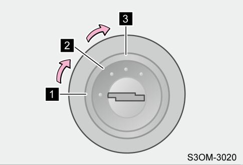
LOCK
Steering wheel is locked and the key can be removed.
In order to lock steering wheel, remove the key and turn steering wheel until it locks.
If the key cannot be turned when unlocking steering wheel, turn the key while lightly turning steering wheel to left and right.

ACC
Some electrical components are available.

ON
Switch power switch to this position without depressing brake pedal. At this time, low voltage appliances of the vehicle can operate normally.
Depress brake pedal and switch power switch to ON, or depress brake pedal when it is in ON, then vehicle enters READY condition, high voltage operation circuit is turned on, and drive motor is ready.
Starting and Operating
Normal Starting and Turning Off
Starting Vehicle
Step 1: Check that the parking brake is applied. Step 2: Check that shift lever is shifted to N.
Step 3: Insert the key, switch power switch to ON, depress brake pedal until READY indicator on instrument cluster comes on.
Turning off EV system
Step 1: Vehicle is completely stopped.
Step 2: The shift lever is shifted to N.
Step 3: Apply parking brake.
Step 4: Turn off power switch to turn off EV system.
If READY condition cannot be entered
If READY indicator on instrument cluster does not come on, it indicates that vehicle does not enter READY condition. Check if power switch is in
ON and brake pedal is depressed.
When power switch is in ACC or ON, if instrument cluster indicates nothing, 12 V battery power may be insufficient, and 12 V battery needs to be charged. It is recommended to contact the local service station.
Parking
Turn power switch to LOCK position and remove the key before leaving the vehicle. Turn steering wheel until steering wheel is locked.
Apply the parking brake completely when parking on a slope, and check that doors and windows are completely closed before leaving the vehicle.
Shift Control
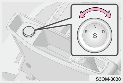
Depress brake pedal, and lightly turn shift knob to switch to required gear position. Current gear position is displayed on instrument cluster. The corresponding gear position indicator on knob also comes on.
When vehicle is in READY condition and is stationary, depress brake pedal to switch shift knob to D or R.
When vehicle is in READY condition and power switch is switched from ON to ACC, if gear position is in N, it will remain in N; If gear position is in R or
D, it will switch to N.
| Gear Position | Function |
| R | It means reverse position. Switch to R when reversing, and ensure that vehicle is stopped completely and brake pedal is depressed. |
| N | It means neutral position. Vehicle moves neither forward nor backward. Switch to N when vehicle is parked. The default gear position is in N when power switch is turned on. |
| D | It means forward driving position. When switching to D, first depress brake pedal. |
Driving Mode
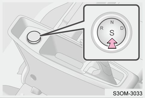
Press the driving mode button S (ECO mode by default) on the shift switch to switch between ECO mode and SPORT mode. When S indicator comes on, it is in SPORT mode; When S indicator goes off, it is in ECO mode.
The motor speed will be reduced in ECO mode, improving the vehicle power economy. At this time, the maximum speed limit is 70 km/h.
The motor will keep a higher speed in SPORT mode, bringing faster power response speed to the driver, but the power consumption is large in SPORT mode. At this time, the maximum speed limit is 90 km/h.
Pedestrian Reminder System
Because the noise of pure electric vehicles is relatively low when driving at low speed, it is difficult for pedestrians nearby to perceive it. In order to improve driving safety, pedestrian reminder system can send alarm sound with different frequencies when vehicle moves forward or reverses and vehicle speed is less than 20 km/h to remind pedestrians nearby to perceive it.
Braking Energy Recovery
When vehicle is driving and reaches specified speed, release accelerator pedal or depress brake pedal. When the system judges that the energy recovery conditions are met, the vehicle performs energy recovery. Convert the mechanical energy during driving into power and store it in the power battery to increase the driving mileage.
When any of the following conditions occurs, energy recovery cannot be performed:
- When the power battery is more than 95%.
- When ABS is enabled to operate or ABS communication is overtime.
- When the vehicle speed is less than 15 km/h.
Steering System
Electric Power Steering System (EPS)
Electric power steering system provides steering power for vehicle. The system does not need power steering fluid, which is very convenient to the daily vehicle maintenance.
EPS malfunction indicator comes on for a short time when power switch is turned on. If EPS malfunction indicator does not go off or comes on during driving, it indicates that EPS system is malfunctioning.
When the electric power steering system works under high load for a long time (for example, keep the steering wheel at the limit position for a long time or move the vehicle to the warehouse repeatedly at low speed with large angle), it may trigger the heat protection function due to the excessive temperature of the electrical appliances.
After entering heat protection condition, the system will decrease steering power, at this time, you need more force to turn steering wheel. If it is necessary to restore normal steering power, turn steering wheel with small angle or increase vehicle speed, and restart vehicle if necessary.
Brake System
Parking Brake System
Usage methods
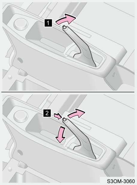

Apply parking brake
Depress brake pedal. Confirm that the vehicle is stationary while parking brake lever is completely pulled up.

Release parking brake
Depress brake pedal. Press lock button while lifting slightly then lower parking brake lever.
Foot Brake
Brake system is designed for brake performance in a wide range of driving conditions. Braking processing reduces speed through brake friction and the friction between tire and ground. The slight friction sound and the friction sound between tire and ground during braking are normal and it is not necessary to need special treatment; Occasional squeal is also normal when braking. Because other substances may adhere to the friction surface during the use of the vehicle, the friction surface may be rust when the vehicle is not used for a long time or after raining, which may cause squeals. As long as the frequency of squeal is not high, it does not need special treatment.
If the brake temporarily loses braking due to overheating, park the vehicle in a safe area and wait for the brake to cool down.
If the brake temporarily loses braking due to wet components, restore its normal performance according to the following steps:
Step 1: Check if there are vehicles behind.
Step 2: Keep safe driving speed, ensure there is enough space behind and on both sides.
Step 3: Depress the brake carefully until the normal performance is restored.
Anti-lock Brake System (ABS)
Anti-lock brake system helps to avoid vehicle slippery and loss of control, and provides maximum braking on slippery roads.
ABS malfunction indicator comes on for a short time when power switch is turned on. If ABS malfunction indicator does not go off or comes on during driving, it indicates ABS is malfunctioning. Please contact the local service station immediately.
ABS system will monitor the speed of each wheel in event of braking. If one wheel tends to lock up, the system will control the brakes of two front wheels and rear wheels respectively. When ABS operates, brake pedal usually vibrates slightly with noise.
Electric Brake Force Distribution (EBD) system
EBD uses a high-speed computer to sense and calculate the different ground surface attached to the four tires at the moment of vehicle braking, and obtain different brake friction values, which allows the four tires can brake in different ways and forces according to different situations, and continuously adjust at high speed in movement, so as to ensure the stability and safety of the vehicle.
Operation Safety
- Non-professional maintenance personnel are strictly prohibited to touch, remove/install or replace any component in the high-voltage system at will to avoid electric shock.
- High voltage cables in vehicle are covered by yellow bellows. Non-professional personnel to insert/unplug high voltage cable connectors.
- Non-professional personnel other than Beijing Automobile Works Co.,Ltd. are strictly prohibited to disengage the power battery.
- Never use organic solvent to clean the power battery housing, which may damage the surface insulation coating and form insulation trouble.
- Never put metal appliances together with battery assembly, and do not park the vehicle in an area with sparks splashing or in a flood area.
Fault Protection
Automatic Power-Off Protection After High Voltage Malfunction
The vehicle is equipped with high voltage malfunction automatic power-off protection function. When high-voltage components of the vehicle are malfunctioning, the vehicle will automatically cut off the high voltage power supply in order to protect the persons in the vehicle.
Automatic Power-Off Protection After Collision
When vehicle is involved in a collision and the relative speed reaches the set threshold, the vehicle will automatically cut off the high voltage, and vehicle system malfunction warning indicator, left and right turn signal indicators on instrument cluster will come on at the same time.
Driving Assistance
Hill Hold Control System
After the vehicle is stationary on a hill, when starting, it is affected by the hill angle and gravity, when the moving backward force is greater than the driving force, the vehicle will stop moving for 5 seconds (motor in D gear has a negative speed and motor in R gear has a positive speed). At this time, the vehicle controller adjusts the output torque to stop moving for 5 seconds and then the vehicle moves backward.
- After activating hill hold control system, if perform any of the following operations, it will exit hill hold control system automatically:
- Shift the gear position to N or switch between D or R gear.
- The vehicle speed is higher than the creep speed on the flat ground
- When the vehicle moves backward after exiting hill hold control system, perform any of the following operations, hill hold control function system will be activated again:
- When the vehicle is stopped by depressing brake pedal, accelerator pedal or applying parking brake, if parking brake, accelerator pedal or brake pedal is released, the hill hold control system will be activated again after the vehicle moves backward slightly.
Parking Assist System
360 Around View System (If Equipped)
360 around view system collects surrounding images of the vehicle through cameras to assist the driver to park safely and easily.
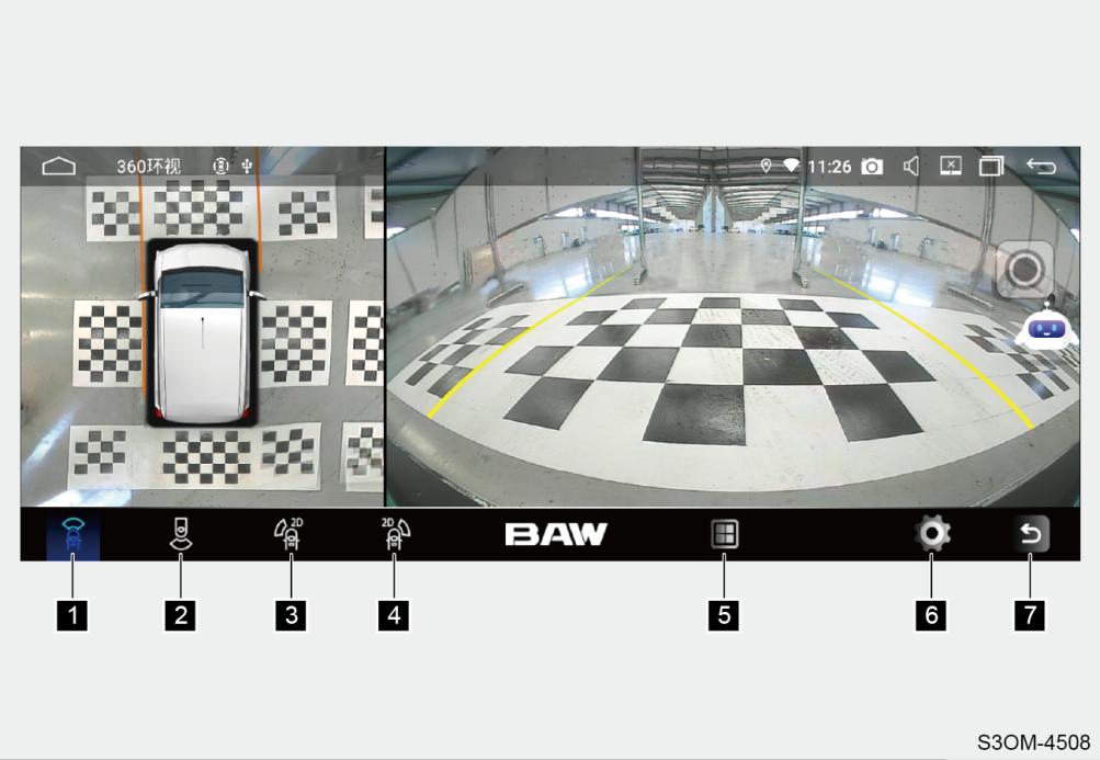
Birds-eye view + front view  (dynamic view is set by default)
Birds-eye view + rear view  (dynamic view is set by default)

Birds-eye view + left view
Birds-eye view + right view

Four split screen

Setting

Exit 360 around view
Usage methods
Turn the power switch to ON to enter 360 around view system interface, and display the 360 around view.
Non-splicing mode
- Four view mode
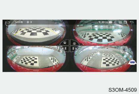
- Back-up rear view
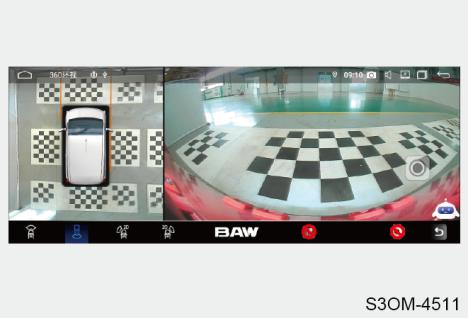
360 around view system setting
Panoramic view setting:
- Starting up rotation: To ensure safety, 360 will rotate by one circle and check the view around vehicle whenever it is powered on.
- Vehicle bottom picture: Diagonal stripe/cloud gray/miracle black/gradient black, gradient black is set by default.
- Turning follow-up: OFF/permanently ON.
- Radar display method: 2D.
- Enabled by radar: ON/OFF, OFF is set by default.
- Driving track: Four different track styles, the style is 2 by default.
- Front view of driving track: ON/OFF, OFF is set by default.
- Rear view of driving track: ON/OFF, ON is set by default.
- Ruler line: ON/OFF, OFF is set by default.
- Enabled by double flashing: 360 is enabled when turning on double flashing, OFF is set by default.
- Left and right view: Left and right 2D view, calibrated/original view, the calibrated view is set by default.
- Standby time: 360 interface standby time, 5 seconds/15 seconds/30 seconds/1 minute, 15 seconds is set by default.
Working disk
The system is Type-C1 by default, the corresponding 360 video recording, upgrading, and import and export of splicing data will operate according to the working disk selected by the customer.
System setting
- Version information: View the version information of current 360 panoramic.
- Reset factory setting: Select this option, all 360 setting will all restore to factory setting, video recorded in U disk will be stored.
Parking Radar System (If Equipped)
The parking radar system speaker will sound at different frequencies according to the distance change of obstacles entering the detection area, and the corresponding display will be displayed on the meter. When using this system, be sure to pay attention to the surrounding area.
Turning on parking radar system
Front parking radar: When turning power switch to ON, shifting the gear position to D and the vehicle speed is less than 15 km/h, the front parking radar is turned on. When vehicle speed is higher than 15 km/h, the system does not work. When the gear position is in N, the system does not work.
Rear parking radar: When turning power switch to ON and shifting the gear position to R, the rear parking radar is turned on.
Parking radar system works only when the vehicle starts, and the system does not work after the vehicle returns to low speed from high speed.
Turning off parking radar system
When any of the following conditions is met, the parking radar system is turned off.
- When turning off power switch.
- When shifting to the gear position other than D and R.
- When vehicle speed is higher than the certain value.
Sensor detection range
- Distance from obstacle is no more than 30 cm: If obstacles are detected within this range, the speaker will sound for a long time to alert the driver.
- Distance from obstacle is more than 30 cm and no more than 50 cm: If obstacles are detected within this range, the speaker will intermittently sound at a frequency of 8 Hz to alert the driver.
- Distance from obstacle is within 50 cm to 80 cm: If obstacles are detected within this range, the speaker will intermittently sound at a frequency of 4 Hz to alert the driver.
- Distance from obstacle is within 80 cm to 120 cm: If obstacles are detected within this range, the speaker will intermittently sound at a frequency of 2 Hz to alert the driver.
- Distance from obstacle is within
120 cm to 150 cm: If obstacles are detected within this range, the speaker will intermittently sound at a frequency of 1 Hz to alert the driver.
Function limit
- Parking radar system may not work normally in the following conditions:
- When vehicle is on a steep slope.
- When driving in jelly-like snow or rain.
- Low objects such as rocks, etc. cannot be detected.
- Objects higher than bumper cannot be detected.
- Thin objects such as wires, fences and ropes, etc. cannot be detected.
- When vehicle is equipped with a high frequency radio or antenna is in use.
- When the surface of the radar sensor is frozen.
- Radar sensors may not operate properly in hot or cold weather.
- When radar sensors are covered by dirt, snow or mud, they may not detect obstacles.
- Objects that easily absorb ultrasonic waves (such as soft snow, cotton, sponge) cannot be detected.
- When there is noisy near the vehicle, such as vehicle horns, motorcycle engines, air brakes of large vehicles, or other loud noises producing ultrasonic waves.
Cleaning radar sensor
When washing vehicle, use a soft cloth or water (low water pressure) to wash off foreign matter such as snow, mud, and dust on the surface of radar sensor.
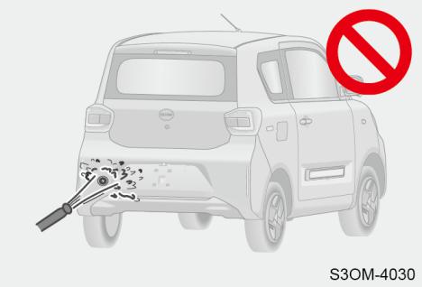
High pressure water flow such as water guns or large external forces may damage the radar sensors. Do not pinch or impact the radar sensors, otherwise the sensors will not work normally.
Tire Pressure Monitoring System (TPMS)
General description
Tire pressure monitoring system can monitor the tire condition through the sensor that is installed in the tire in real-time. If the problems such as undervoltage, overvoltage, rapid air leakage and system failure etc. occur, please inform user to handle it in time.
Tire Pressure Monitoring System
(TPMS) is an assist system, which can monitor tire pressure parameters in real-time, display and alarm via visual signal (which may include audible signal) to improve vehicle driving safety, and reduce the tire acceleration wear and vehicle energy consumption increase caused by low or high tire pressure.
- The following is the role of Tire Pressure Monitoring System (TPMS)
- Remind the driver that the tire is malfunctioning to avoid serious accidents.
- Reduce wheel wear and extend the tire service life. Some data shows that when driving with insufficient tire pressure, the tire pressure drops by 10% compared with the normal value and the tire service life reduces by 15%.
- When driving with excessive tire pressure, the damping effect of the tire itself will be reduced, resulting in increasing the burden of the vehicle damping system. Long-term use will cause great damage to the chassis and suspension system; If the tire pressure is uneven, it will also cause the brake to deviate, thus increasing the wear of the suspension system.
Handling Vehicle In Emergency
Spare Tools
Charging gun and towing hook are located in the luggage compartment.
If 12 V Battery is Depleted
Jump-starting
If there are a set of jumper cables and another vehicle with a 12 V battery, please follow the following steps to jump start the vehicle.
Step 1: Open the front compartment cover.
Step 2: Connect jumper cables according to the following steps:
Connect the positive clamp on jumper cable to positive terminal (+) of the vehicle battery.

Connect the clamp on another end of positive cable to positive terminal (+) of another vehicle battery.

Connect the negative cable clamp to negative terminal (-) of another vehicle battery.
Connect the clamp on another end of negative cable to the solid, fixed, unpainted metal part.
Step 3: Start another vehicle to charge battery of the vehicle.
Step 4: Switch power switch of this vehicle to ON, and then start the vehicle.
Step 5: After the vehicle starts successfully, remove jumper cable in the reverse order of connection.
Note: After the vehicle starts, please go to the local service station for inspection and repair as soon as possible.
Towing
If the vehicle needs to be towed, Beijing Automobile Works Co.,Ltd. recommends to use lift-type truck or flatbed truck, and it is towed by the local service station or professional rescue company.
Always tow with safety chain devices and follow all national/provincial regulations.
Installing Towing Hook
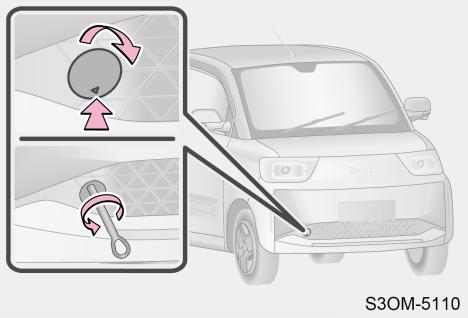
Step 1: Press the lower part of towing hook trim cover to open front towing hook trim cover.
Step 2: Install towing hook into towing hook hole in a counterclockwise direction. Then tighten it firmly with tools.
Towing Vehicle
Tow with wheel lift-type truck from front
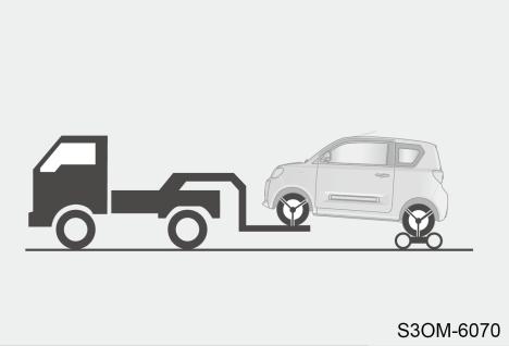
Place towing dolly under rear wheels.
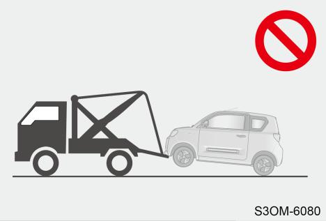
Never towing with sling-type truck
Do not tow with sling-type truck to avoid damage to vehicle body.
Using a flatbed truck
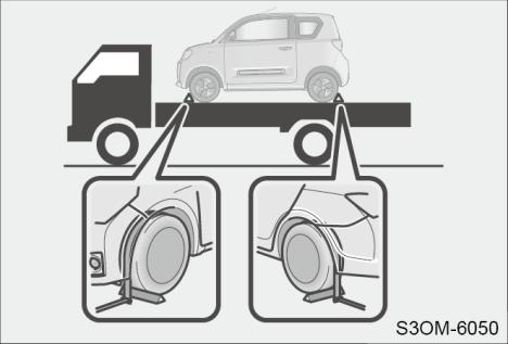
- Apply parking brake, and turn power switch to OFF.
- Put blocks under 4 wheels to avoid vehicle from moving.
- Attach the tire to the bottom plate of trailer to fix the vehicle as shown in the illustration.
If flatbed truck is not available during towing, your vehicle may be temporarily towed using a towing hook. This should only be attempted on hard surfaced road for short distances at low speed.
Following conditions must be met when towing vehicle using a towing hook:
- Turn power switch to ON.
- Gear position is changed to N.
- Release parking brake.
During towing the vehicle, the vehicle speed should not exceed 30 km/h and the driving mileage should not exceed 50 km. Otherwise, the electric drive or high voltage parts may be damaged.
If the following conditions occur, the vehicle must be towed by flatbed truck:
- The vehicle cannot be driven, power switch is in ON, warning light and indicator do not come on.
- The braking effect is increasing or the brake pedal has a pulsating feeling.
- It is confirmed that there has a mechanical failure in drive train.
Accident Handling
Due to the particularity of pure electric vehicle (the vehicle is equipped with power battery and high voltage system), therefore, be sure to comply with the following requirements in the event of an accident with pure electric vehicle.
Collision
In case of a collision, please turn on hazard light immediately, and place hazard warning sign behind the vehicle according to the regulations and provisions to avoid following accidents.
- Please go to the local service station immediately to confirm vehicle malfunction state and consult handling suggestions, and then contact the insurance company for handling.
- In case of serious collision (airbag deployment), the vehicle control system will automatically cut off the high voltage system of the vehicle, and the vehicle cannot continue driving. At this time, observe the following precautions:
- Never touch the exposed wires when they are found inside and outside the vehicle. Failure to do so may cause an electric shock. Never touch the high voltage parts, orange high voltage cables and its connectors in vehicle. Failure to do so may cause serious injuries or death caused by electric shock.
- If fluid leakage occurs or fluid flows into components in vehicle, never touch this kind of fluid, which may be the fluid leaked from power battery. In the unlikely event that it comes into contact with the skin or eyes, wash it off immediately with a large amount of water and seek immediate medical attention to avoid greater harm.
- If it cannot confirm whether the vehicle is damaged and safe, leave vehicle at this time. Be sure to inform the emergency persons who come to deal with the accident at the first time that the vehicle is an electric vehicle. Do not allow any other person to approach, contact or move the vehicle.
- In the event of an accident causing a vehicle fire, immediately leave the vehicle and go to a safe area, call the local fire call to inform the fire department, and contact the local service station.
Water Accident
Turn off power switch and leave the vehicle in time when the vehicle is submerged in water in part or in whole. If there are no bubbles or sizzle during salvaging, the salvage work can be performed. If there are bubbles or sizzle, the salvage work only can be performed after there are no bubbles or sizzle. Using specialized equipment, operate salvage work by specialists.
Fire Accident
If fire occurs, leave vehicle immediately, perform following operations conditionally under the condition of ensuring personal safety:
- Call the police according to the site situation, and contact the local service station.
- If it can be confirmed that the fire is small and does not involve high voltage system, try to extinguish the fire with a special fire extinguisher for electrical fire (water-based fire extinguisher); Otherwise, immediately leave the vehicle and stand at the upper air outlet, and inform the firefighters quickly. Do not extinguish the fire with water by yourself to avoid the risk of electric shock.
- If someone accidentally inhales thick smoke, please transfer the person and seek medical attention as soon as possible.
Maintenance
Care and Maintenance
Cleaning and Protecting Vehicle Exterior
The following operations can be performed to protect the vehicle and keep it in good condition:
- Rinse the body, wheel wells and underside of the vehicle with plenty of water from top to bottom to remove dirt and dust.
- Scrub the body with a sponge or soft cloth, such as a chamois.
- For marks that are difficult to remove, use washing agent to clean and rinse thoroughly with water.
- Wipe off the water.
- Wax the vehicle when the waterproof coating deteriorates. If water does bead cannot form on the clean surface, apply wax when the vehicle body is cool.
Washing vehicle
- Rear view mirrors should be folded before washing the vehicle. Start washing from the front of the vehicle. Be sure to extend the mirrors before driving.
- Brushes used in automatic car washing station can scratch vehicle surfaces, parts (wheels, etc.) and damage the paint.
Wheel hub and hub trims
- Immediately remove all dirt with neutral detergent.
- After using detergent, rinse immediately with water.
Bumper
Do not scrub with abrasive cleaners.
Underbody maintenance
Corrosive substances used in melting ice, snow and dust can collect on the underbody. Failure to remove these substances will accelerate corrosion and rust.
Rinse the underbody regularly with clean water. Carefully clean areas prone to collect the dirt. Loosen accumulated dirt in enclosed areas before rinsing with water.
Prevent from paint deterioration, corrosion of body and components (steel wheel hub, etc.)
If the paint is peeling or scratched, repair it immediately.
To prevent the wheels from corroding, remove any dirt and store in a place with low humidity when storing the wheels. In the following situations, the vehicle should be washed immediately:
- After driving by the sea
- After driving on saline-alkali road
- If coal tar or tree sap is present on the paint surface
- If dead insects, insect droppings or bird droppings are present on the paint surface
- After driving in an area contaminated by soot, oily smoke, mine dust, iron powder or chemical substances
- If the vehicle becomes heavily soiled with dust or mud
- If liquids such as benzene and gasoline are spilled on the paint surface
Cleaning and Protecting Vehicle Interior
- Remove dirt and dust using a vacuum cleaner. Wipe dirty surfaces with a cloth dampened with lukewarm water.
- If dirt cannot be removed, wipe it off with a soft cloth dampened with neutral detergent diluted to approximately 1%. Wring out any excess water from the cloth and thoroughly wipe off remaining traces of detergent and water.
Cleaning the carpets
A variety of commercially available foam cleaners can be used. Use a sponge or brush to apply the foam. Scrub in overlapping circles. Do not use water. Wipe up the dirty surface and let it dry. Keep the carpet as dry as possible for best results.
Detergent
Do not use polishing wax or polishing cleaners. Otherwise, the painted surface of the instrument panel or other interior parts may be damaged.
Do not use the following types of detergents, which may cause discoloration or staining or damage to the interior of the vehicle:
- Non-seat parts: Organic substances such as benzene or gasoline, alkaline or acidic solutions, dyes and bleaches
- Seats: Alkaline or acidic solutions, such as thinner, benzene, and alcohol
Prevent damage to the leather surface
Observe the following precautions to avoid damage and deterioration of leather surfaces:
- Remove any dust or dirt from leather surfaces immediately.
- Do not expose the vehicle to direct sunlight for a long period of time. Please park the vehicle in a shaded place, especially in summer.
- Do not place polyethylene, plastic products or wax-containing items on the leather trim, as they may stick to the leather surface if the vehicle interior heats up significantly.
Maintenance Notice
There are two types of repair and maintenance: One is normal maintenance, which can be done by the customers; the other is regular maintenance, inspection and repair, which need to be completed by the local service station.
For the details of regular maintenance, inspection and repair methods, please refer to “Regular Maintenance” in this section; Regular maintenance can be helpful for you to found and eliminate potential dangers in time to prevent malfunctions. Scheduled maintenance of your vehicle is essential. Please strictly follow the maintenance schedule of “User Manual” to perform maintenance, ensuring that your vehicle maintains the best performance and good operating conditions, thus effectively extending the service life of the vehicle.
Please use the oil fluid recommended by Beijing Automobile Works Co.,Ltd., or vehicle may be damaged.
The service station is equipped with advanced maintenance tools, equipment and genuine spare parts required to provide maintenance and service to your vehicle. And all after-sales service personnel have received professional management and technical training to ensure fast and efficient completion of vehicle maintenance and repair work, to ensure that your vehicle always has good technical performance.
Rubber hoses used for braking systems, etc., should be inspected by professionals in strict accordance with the maintenance schedule. Rubber hoses will deteriorate with age, resulting in swelling, wear or cracking. Therefore, if the hose is deteriorated or damaged in any way, please contact the local service station immediately for replacement.
Does your vehicle need repairs?
Be alert for changes in vehicle performance and sound, as well as visual symptoms that indicate your vehicle needs repairs. The following are some important signs:
- Significant loss of power
- Abnormal noise
- Liquid leakage from the bottom of the vehicle (However, it is normal for air conditioning systems to drip water after use.)
- Flat-tires, excessive tire noise when cornering, uneven tire wear
- Vehicle pulls to one side when driving straight on a level road
- Abnormal noise related to suspension movement
- Loss of brake effectiveness, soft brake pedal, pedal almost touching the floor, pulling to one side when braking
If you notice any of above signs, please take your vehicle to the local service station as soon as possible.
Normal Maintenance
Many maintenance items are not complicated, as long as user has a little mechanic knowledge and some basic vehicle tools, they can be completed by the user. This section will briefly explain how users can perform simple maintenance. It should be noted that some maintenances require special tools and expertise. These maintenances are best done by qualified technicians. Even if you have rich maintenance experience, we still recommend you to go to the local service station for standardized repair and maintenance. They will record the maintenance information of your car and help you apply for a warranty service.
Checking Brake Fluid Level
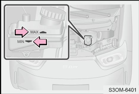
Brake fluid level should be between the MIN and MAX marks. If the level is at or below the MIN mark, add brake fluid.
Checking Tires
Check the condition of the tires before driving and check the tire pressure at least once a month.
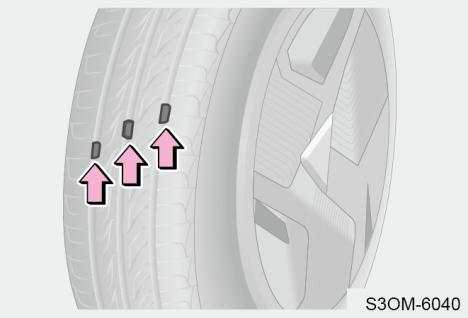
Check the tire tread by the tread wear mark. When tread wear reaches its limit, tread will be in the same plane as the wear band. At this time, it indicates that performance and safety of tire seriously decrease, and replacement is necessary.
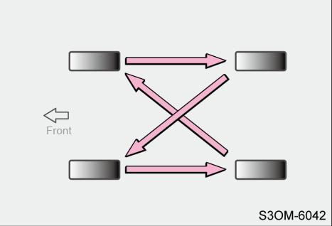
To equalize tire wear and help extend tire life, it is recommended that you perform a tire rotation every 12 months or 10,000 km (whichever comes first).
When to replace tire
In the following situations, the tire should be replaced:
- The tire shows the tread wear mark.
- A tire goes flat repeatedly or cannot be properly repaired due to the size or location of a cut or other damage.
- When the tire has damages such as cuts, breaks, deep cracks exposing the fabric, or bulges that indicating damage inside the tire.
- Observe the following precautions. Failure to do so may lead to an accident, resulting in death or serious injury:
- Do not use tires that were used on another vehicle.
- Do not mix tires with remarkably different tread wear.
- Do not use tires if you do not know how they were used previously.
- Do not mix tires with different manufacturers, models or tread patterns.
- Do not mix differently constructed tires (such as radial bias-belted or bias-ply tires).
- Be sure to keep proper tire pressure. Otherwise, the following conditions may occur and result in death or serious injury:
- Excessive wear.
- Poor handling.
- Uneven wear.
- Poor sealing of the tire bead.
- Wheel deformation or tire separation.
- Possibility of blowouts resulting from overheated tires.
- A greater possibility of tire damage caused by poor road conditions.
Checking 12 V Battery
Check and make sure that the battery terminals are not corroded and that there are no loose connections, external cracks, or loose fixing clamps.
Chemicals in the battery
12 V battery contains poisonous and corrosive sulfuric acid and may produce hydrogen gas which is flammable and explosive. To reduce the risk of serious injury or even death, observe the following precautions when working on or near 12 V battery:
- Do not cause sparks by touching the battery terminals with tools.
- Do not smoke or light a match near the battery.
- Avoid contact with eyes, skin and clothes.
- Never inhale or swallow electrolyte.
- Wear protective safety glasses when working near the battery.
- Keep children away from the battery.
Checking Windshield Washer Fluid
If no washer fluid is sprayed from washer nozzles, stop operating washers and check if it is necessary to add washer fluid. If it cannot operate properly after adding washer fluid, please contact the local service station for inspection and repair.
Checking Wiper Blades
Check the roughness of wiper blade by sliding on its edge using your finger. If it is too rough, the wiper blade will not work effectively.
Maintaining wiper blades
- Do not use high-pressure water jet to directly wash the wiper blades while washing the vehicle, otherwise the wiper blades could be deformed.
- In order to prevent the formation of schlieren, it is recommended to clean wiper blades using glass detergent regularly once a week.
- Apply pure water to rinse the windshield and blades after washing the vehicle in the automatic car washer, which can remove the remaining wax layer.
- Do not operate wiper blades when windshield is dry. Doing so may scratch glass, resulting in permanent damage to wiper blades.
- Do not clean the windshield with fuel, nail polish remover, paint thinner or similar liquid, which can damage the wiper blades.
- Avoid using glass agent and hydrophobic agent on the front windshields. The hydrophobic layer will fall off slowly after using, resulting in uneven friction of windshield and abnormal noise of wiper shaking.
- When the windshield surface is frosted or frozen, or when dry soil, insect, sticker or other solid particles are attached to the windshield surface, clean them with a wet cloth in time. Do not use a dry cloth or remove them with wiper blades directly, otherwise it will damage the windshield and wiper blades.
Using wipers
- Do not swing the wiper arm manually, otherwise it may damage the wiper.
- When there is snow, leaves, branch and other objects, they should be cleaned before operating the wiper.
- Washer fluid should be added on time, and do not use tap water instead.
- In cold weather, always check if the wiper blades are frozen on the windshield before using. If they are frozen on the windshield, always unfreeze them before using. Use air conditioning heating and ventilation device to warm up. Do not pour hot water directly to blades, otherwise, windshield may break or wiper blades may deform.
Regular Maintenance
Regular Maintenance Regulations
All matters specified in this system apply to vehicles within the warranty period. For vehicles beyond the quality guarantee period, it is only a suggestion or reference.
- The first maintenance is 6 months or 5,000 km (whichever comes first). Within 6 months or 5,000 km (whichever comes first),
- We recommend that users perform each maintenance at the local service station. After the maintenance is completed, the "Maintenance record sheet" will be filled in by the local service station, and the user will sign it after confirmation.
- For quality problems found in inspections during maintenance operation, follow the specifications of quality guarantee service.
- The maintenance specification list specifies the date and mileage of each maintenance. Under the warranty, it must be maintained at the local service station according to the date specified in the maintenance specification list. After the maximum quality guarantee period, it is recommended that you also go to the local service station to perform appropriate maintenance according to the date and mileage intervals (or earlier as necessary) in the maintenance specification list.
Normal Maintenance Specification List
- The first maintenance: It should be carried out within 6 months or 5,000 km after purchase, whichever comes first; Replace the decelerator gear oil during the first maintenance.
- Regular maintenance requirements: After the first maintenance, the subsequent maintenance interval is every 12 months or every 10,000 km, whichever comes first.
- Normal maintenance specification list: When the vehicle is driven in an environment with flat roads and little dust, it should be maintained in accordance with the requirements in the normal maintenance specification list or earlier as necessary. Date and mileage whichever comes first. The key components replacement and maintenance specifications are as shown in the following table:
| Normal Maintenance Specification List | ||||||||||||
| Category | Items Interval | Time (months) | 6 | 18 | 30 | 42 | 54 | 66 | 78 | 90 | 102 | 114 |
| × 1,000 km (kilometers) | 5 | 15 | 25 | 35 | 45 | 55 | 65 | 75 | 85 | 95 | ||
| Replacement and overhaul | Decelerator gear oil | R | R | R | R | R | R | R | R | R | R | |
| Brake fluid | I | I | R | I | I | R | I | I | R | I | ||
| Grease the steering column dust cover | I | I | I | I | I | I | I | I | I | I | ||
| Door lock, hinge and stopper lubrication | I | I | I | I | I | I | I | I | I | I | ||
| Normal Maintenance Specification List | ||||||||||||
| Category | Items Interval | Time (months) | 6 | 18 | 30 | 42 | 54 | 66 | 78 | 90 | 102 | 114 |
| × 1,000 km (kilometers) | 5 | 15 | 25 | 35 | 45 | 55 | 65 | 75 | 85 | 95 | ||
| Inspection of battery, motor and electronic control system | Appearance status of power battery assembly box and its connector and protector | I | I | I | I | I | I | I | I | I | I | |
| High voltage wire harness and its connection status of each high voltage component, drive motor and motor controller low voltage control wire harness | I | I | I | I | I | I | I | I | I | I | ||
| Appearance, connector and cooling status of on-board three-in-one (charger, DCDC converter, distribution box) | I | I | I | I | I | I | I | I | I | I | ||
| Power battery assembly system parameters | I | I | I | I | I | I | I | I | I | I | ||
| Vehicle control system | I | I | I | I | I | I | I | I | I | I | ||
| Normal Maintenance Specification List | ||||||||||||
| Category | Items Interval | Time (months) | 6 | 18 | 30 | 42 | 54 | 66 | 78 | 90 | 102 | 114 |
| × 1,000 km (kilometers) | 5 | 15 | 25 | 35 | 45 | 55 | 65 | 75 | 85 | 95 | ||
| Chassis and brake inspection | Chassis fastener torque | I | I | I | I | I | I | I | I | I | I | |
| Brake inspection: Brake system hard pipes, hoses and related components | I | I | I | I | I | I | I | I | I | I | ||
| Steering system and link, propeller shaft and ball pin boot | I | I | I | I | I | I | I | I | I | I | ||
| Consumable parts inspection | Tires: Tread depth, torque of nut, tire pressure*1 | I | I | I | I | I | I | I | I | I | I | |
| Lighting system, electric horn, wiper | I | I | I | I | I | I | I | I | I | I | ||
Explanation of symbols in the table:
I - Check these items and their related components. Correct, tighten, clean, replenish, adjust or replace if necessary.
R - Replacement or change.
*1 If necessary, perform four-wheel alignment or tire dynamic balancing.
Items in the maintenance schedule should be replaced more frequently than recommended intervals if the vehicle is subjected to the following severe conditions.
- Use the brakes and emergency brake frequently.
- Frequently rapid acceleration, deceleration or high speed driving.
- Often driving in conditions where the outdoor temperature is below 0°C or above 35°C.
- Often driving on dusty roads, hilly or mountainous areas.
- Vehicles used for special purposes such as police cars, taxis, rentals or other operations.
| Irregular Maintenance Specification List | |
| Irregular Maintenance Items | Irregular Replacement Interval |
| Tire rotation | Replace every 12 months or every 10,000 km or earlier as necessary |
| Decelerator gear oil | Replace every 12 months or every 10,000 km or earlier as necessary |
| Brake fluid | Replace every 18 months or every 15,000 km or earlier as necessary |
| Other types of items in the normal maintenance list | According to the normal maintenance list, the maintenance interval will be halved accordingly or based on the halved, it will be earlier as necessary. |
For details of maintenance record sheet, instrument cluster replacement record and owner change record, please refer to the appendix of this manual.
Specification
Label Location
Vehicle Identification Number (VIN)
Vehicle Identification Number (VIN) on actual vehicle
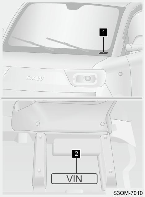

Vehicle identification number label is located on upper left of driver side instrument panel, and can be seen from the outside through the front windshield.

Vehicle identification number is engraved on the floor under the passenger seat. It can be seen after you lift the carpet printed with VIN.
Manufacturer Name Plate
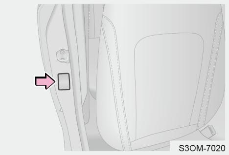
Vehicle product label is located on right quarter outer panel as shown in the illustration.
The contents of the nameplate include: Company name, vehicle identification code (VIN), brand, vehicle model, motor model, motor peak power, rated power, battery model, battery rated voltage, battery rated capacity, vehicle curb weight, number of occupants, maximum allowable total weight, manufacture date information.
Motor
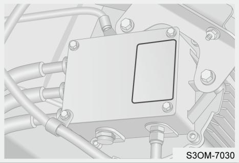
The drive motor nameplate is pasted on the upper surface of drive motor, the contents of the nameplate include: model, number of phases, rated operation voltage, IP grade, peak speed, rated power, peak power, rated torque, peak torque, cooling method, insulation level, duty, company name, etc.
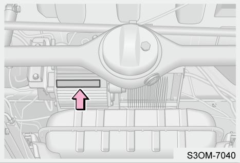
The model and serial number of the drive motor are engraved on the bottom of the drive motor (which can be seen after the vehicle is lifted).
Microwave Window
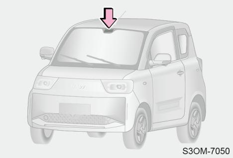
The microwave window is located on the inner side of the front windshield and at the right side to the back of the inside rear view mirror, where is for wireless RF signal transmission and installation of automotive electronic identification.
Vehicle Specifications
Vehicle Dimensions
| Overall Size | Length (mm) | 3162 |
| Width (mm) | 1498 | |
| Height (mm) | 1585 | |
| Wheel Base (mm) | 2050 | |
| Tread | Front (mm) | 1290 |
| Rear (mm) | 1290 | |
| Overhang | Front (mm) | 579 |
| Rear (mm) | 533 |
Vehicle Weight
| Vehicle Model | BAW7000UL46BEV | |
| Vehicle Curb Weight (kg) | 720 | |
| Unladen Axle Load | Front Axle (kg) | 391 |
| Rear Axle (kg) | 329 |
| Laden Axle Load | Front Axle (kg) | 551 |
| Rear Axle (kg) | 489 | |
| Allowable Maximum Total Weight (kg) | 1040 | |
| Driving Mileage (km) at Constant Speed of 60 km/h | 170 | |
| Seating Capacity (Including Driver) (Person) | 2 |
Vehicle Performance and Driving Range
| Minimum Ground Clearance (mm) | 135 |
| Minimum Turning Diameter (m) | 8.5 |
| Approach Angle (°) | 29 |
| Departure Angle (°) | 41 |
| Maximum Vehicle Speed (km/h) | 90 |
| Maximum Gradeability (%) | 17 |
Driving Mode
| Driving Mode | Rear-mounted and rear-wheel drive |
Motor
| Model | TZ160X020 |
| Type | Permanent magnet synchronous motor |
| Cooling Method | Natural air cooling |
| Rated Power (kW) | 13 |
| Maximum Power (kW) | 20 |
| Rated Voltage (V) | 96 |
| Maximum Torque (N·m) | 85 |
| Maximum Speed (r/min) | 7500 |
Power Battery
| Vehicle Model | BAW7000UL46BEV |
| Type | Lithium iron phosphate battery (BMS) |
| Rated Voltage of Power Battery Pack (V) | 102.4 |
| Nominal Capacity of Power Battery Pack (kWh) | 13.7 |
On-board three-in-one
| OBC | AC input voltage range (Vac) | 150 - 264 |
| AC input current (A) | ≤9.6 | |
| Efficiency | ≥93% | |
| Power factor | ≥0.98 | |
| Rated output voltage (Vdc) | 96 | |
| Rated output power (Kw) | 2 | |
| DCDC | Operation voltage range (V) | 65 - 144 |
| Rated power | 800W@25℃ | |
| Maximum output total current (A) | 60 ± 2 | |
| Unladen output voltage (V) | 13.8 ± 0.3 | |
| Laden output voltage (V) | ≥12 | |
| Maximum efficiency | ≥91% |
Suspension System
| Front Suspension | Macpherson type independent suspension |
| Rear Suspension | Three-link type non-independent suspension |
Brake System
| Reasonable Range of Brake Pedal Free Travel | Less than 20 mm |
| Reasonable Range of Use for Brake Friction Pair | Thickness of friction material is 7.5 mm, to be replaced after 5.5 mm wear The initial thickness of the brake disc is 8 mm, to be replaced after 1 mm wear on one side |
Fluids
| Items | Specification | Capacity |
| Brake Fluid | DOT4 | 0.46 ± 0.01 L |
| Rear Axle Gear Oil | GL-5 85W-90 (summer gear oil model) GL-5 80W-90 (winter gear oil model) | 0.8 ± 0.05 L |
| A/C Refrigerant | R-134a | 375 g |
Wheel Alignment
| Front Wheel | Toe-in | 0°- 10′ |
| Camber | 0.38° ± 45′ | |
| Kingpin Inclination | 11.2° ± 1° | |
| Kingpin Caster | 2.8° ± 45′ | |
| Rear Wheel | Toe-in | 0° ± 10′ |
| Camber | 0° ± 0.5° |
Wheel and Tire
| Tire Model | 155/65 R13 | |
| Cold Tire Inflation Pressure (kPa) (Fully loaded) | Front Wheel | 250 ± 20 |
| Rear Wheel | 250 ± 20 | |
| Wheel Dynamic Balance Requirements | Dynamic unbalance ≤10 g |
Battery
| Battery Model | 12V 36Ah |
Steering System
| Steering Power Mode | Electric boost |
| Steering Gear Type | Rack & pinion type |
Light Bulb Specification
| Light Bulb Name | Source/Model | Watt of Light Bulb |
| Headlights | H7 | 55 W |
| Daytime Running Light | LED | 0.5 W × 28 |
| Position Light | LED | 0.2 W × 8 |
| Side Turn Signal Light | WY5W | 5W |
| Rear Fog Light | LED | 0.5 W × 8 |
| Brake Light | LED | 0.5 W × 6 |
| Back-up Light | P21W | 21W |
| Front Turn Signal Light | LED | 0.5 W × 14 |
| Rear Turn Signal Light | PY21W | 21W |
| License Plate Light | LED | 1.2W |
| Dome Light | C5W | 5W |